Golf club head

a golf club head and metal shell technology, applied in golf clubs, sport apparatus, golf, etc., can solve the problems of dramatic decrease of carry, insufficient adaptation of conventional face plates, etc., and achieve the effect of less carry

Inactive Publication Date: 2010-08-31
BRIDGESTONE SPORTS
View PDF22 Cites 21 Cited by
  • Summary
  • Abstract
  • Description
  • Claims
  • Application Information

AI Technical Summary

Benefits of technology

[0008]By such a shape of the face plate, the distribution of hit points of general amateur golfers is covered, so that even for an off-center hit, the decrease in carry is less.

Problems solved by technology

The conventional face plate does not sufficiently accommodate variations in hit points of general amateur golfers.
However, when a ball is hit at a portion deviating from the sweet spot, and further at the face part such as a toe upper portion or a heel lower portion other than the substantially square-shaped, therefore limited, face plate, the carry dramatically decreases.

Method used


Image

  • Golf club head
  • Golf club head
  • Golf club head

Examples


Embodiment Construction

[0017]Preferred embodiments of the present invention will now be described with reference to the accompanying drawings.

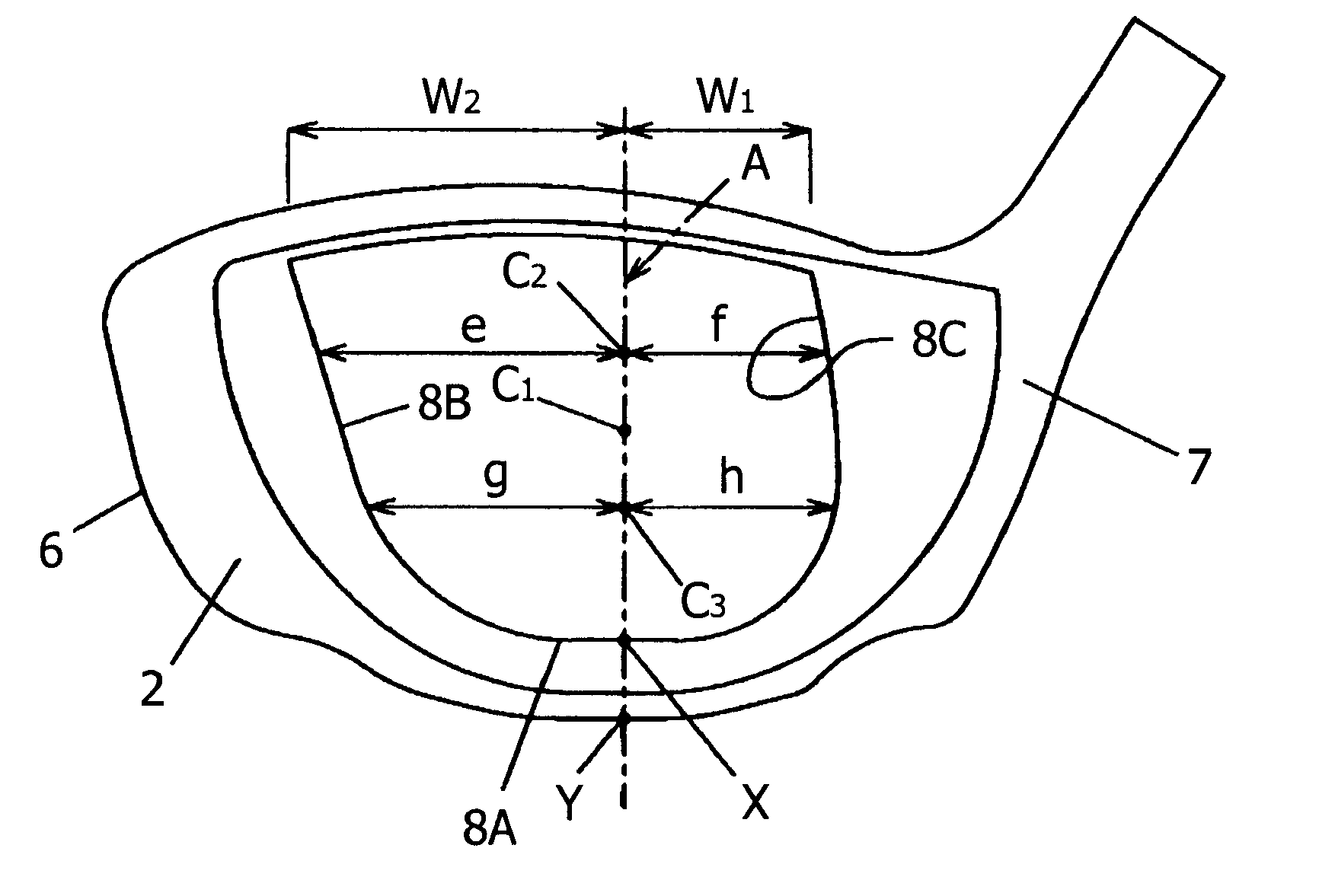
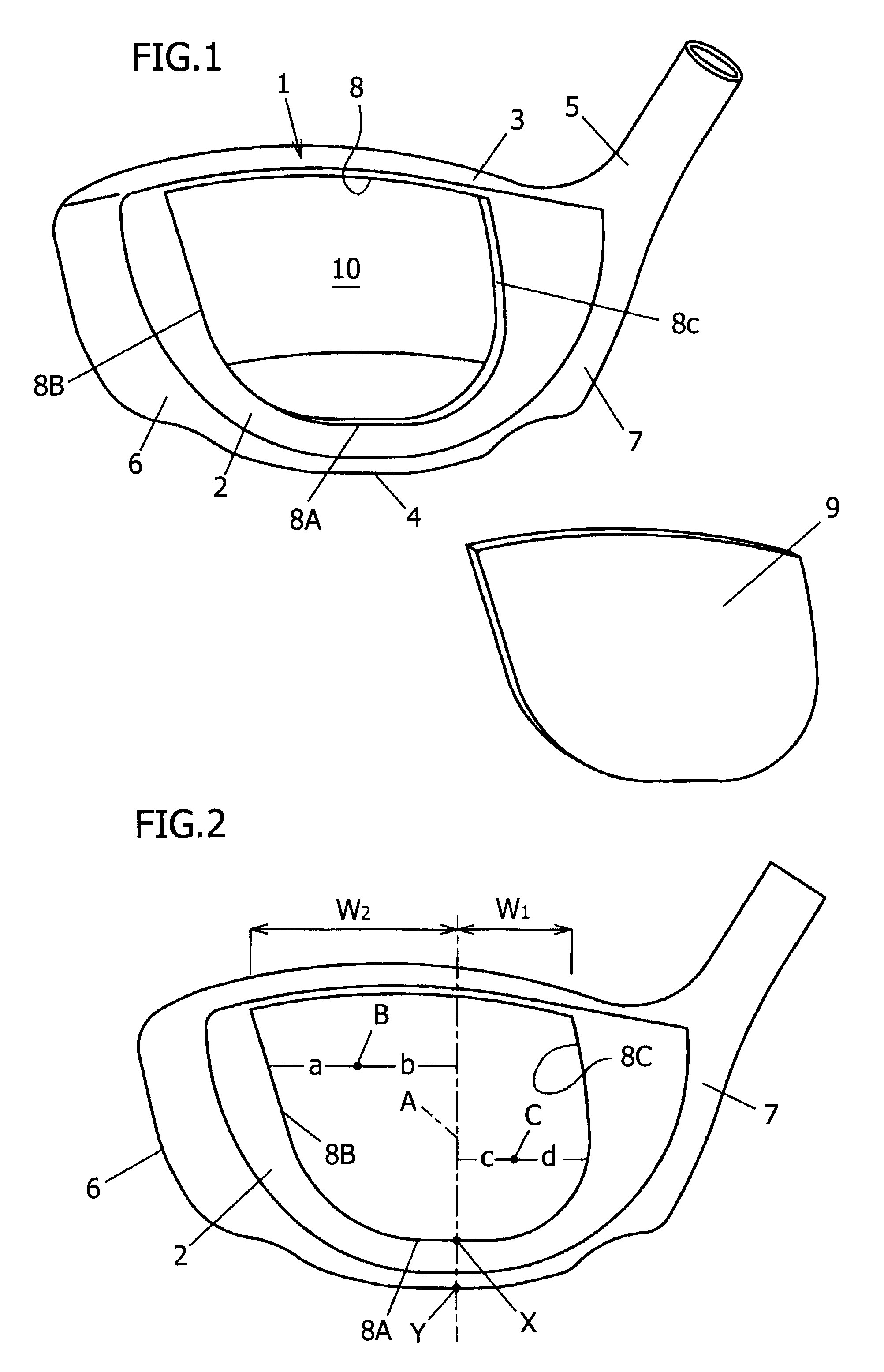
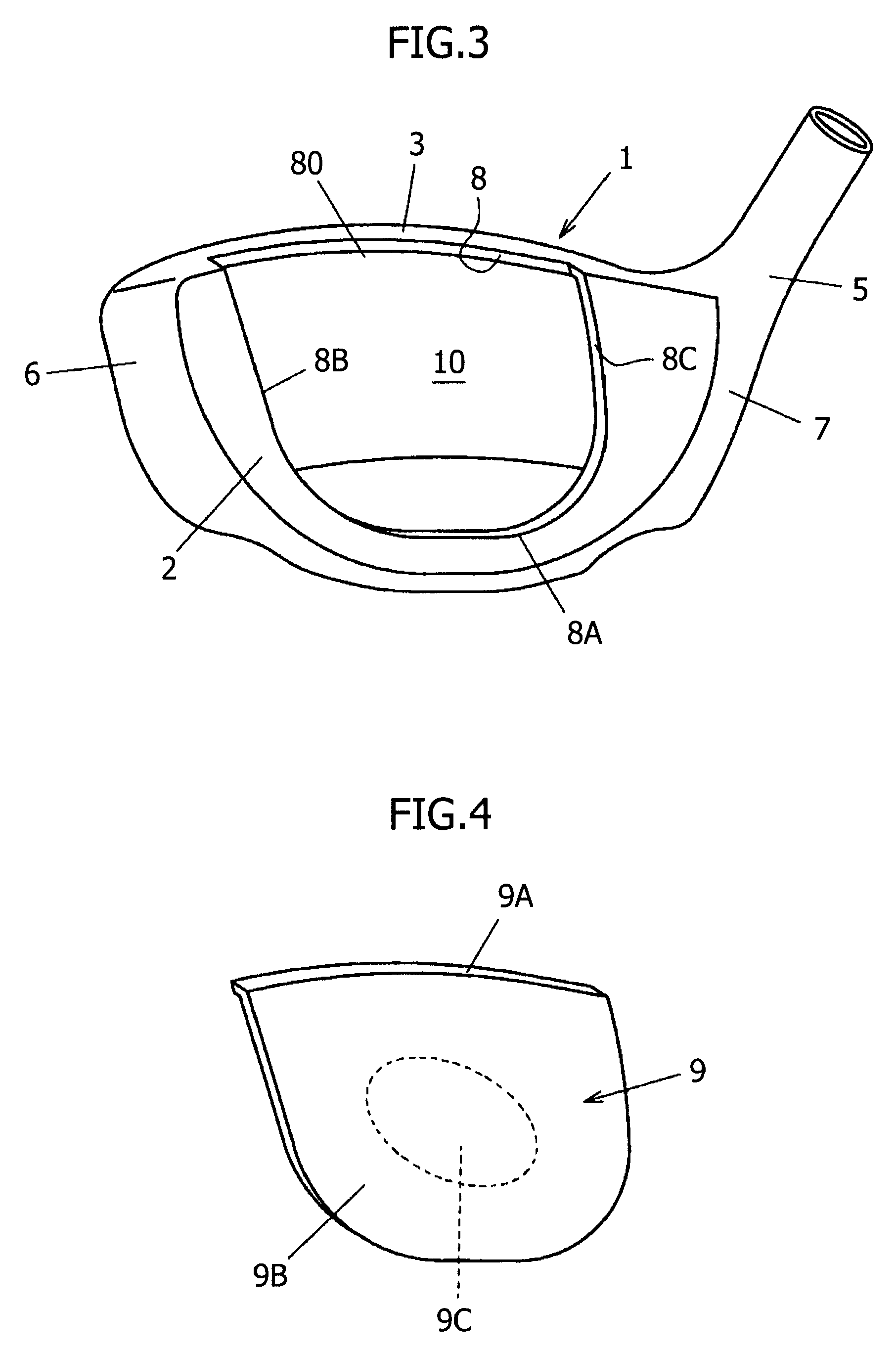
[0018]In FIG. 1, a metallic head body 1 has a cavity 10 therein, and is formed with an opening 8 therethrough to the cavity 10. The head body 1 includes a face part 2, a crown part 3, a sole part 4, and a hosel 5, and has a toe 6 and a heel 7. Unlike the conventional example, the opening 8 does not have a square shape, but is formed into a U shape such that the front shape tilts to the toe 6 side. More specifically, the opening 8 is demarcated by an upper edge along an upper end of the face part 2 and a U shaped curved edge (8B, 8A, 8C) located within the face part 2. A face plate 9 welded to the opening 8 is also formed into a U shape matching the shape of the opening 8.

[0019]The lowermost portion of a bottom edge 8A of the opening 8 is denoted by symbol X in FIG. 2. A portion between left and right side edges 8B and 8C opposed to each other of the opening 8 is the...


PUM


Abstract

A golf club head includes a metallic head body 1 having a cavity 10 therein and an opening 8 being formed in a face part 2 therethrough to the cavity, and a metallic face plate 9 welded to the opening. The opening 8 is demarcated by an upper edge along an upper end of the face part 2 and a U shaped curved edge (8B, 8A, 8C) located within the face part 2, and is also formed so that, in a state in which the head body 1 is soled in accordance with the lie angle, a projection line A on the face part surface of the perpendicular passing through the lowermost portion X of the opening 8 coincides with a projection line A on the face part surface of the perpendicular passing through a ground contact point Y of a sole part 4, or the projection line drawn with the lowermost portion X of the opening 8 being the reference is positioned close to a heel part 7 with respect to the projection line A drawn with the ground contact point Y of the sole part; and the ratio of width W2 on the toe side with respect to the projection line drawn with the ground contact point Y of the sole part 4 is higher than the ratio of width W1 on the heel side toward a crown part. The face plate 9 is formed so as to have a shape matching the opening 8.

Description

FIELD OF THE INVENTION[0001]The present invention relates to a metallic hollow golf club head and, more particularly, to a golf club head in which a face plate is welded to an opening formed in a face part.BACKGROUND OF THE INVENTION[0002]As a conventional metallic hollow golf club head in which a face plate is welded, a golf club head shown in FIG. 8 has been known. In this golf club head, a substantially rectangular opening 20 is formed in a face part 2 of a metallic head body 1 having a cavity 10 therein, and a face plate 30 having a shape matching the opening 20 is laser welded to a receiving part 2b formed at the periphery of the opening 20. The head body 1 includes a crown part 3, a sole part 4, and a hosel 5 in addition to the face part 2, and has a toe 6 and a heel 7. In this conventional example, the welding strength is improved, and therefore damage is less liable to occur (refer to JP 2004-65853 A1).[0003]Also, as a golf club head in which the whole of the face part is a ...

Claims


Application Information

Patent Timeline
Patent Type & Authority Patents(United States)
IPC IPC(8): A63B53/04A63B102/32
CPCA63B53/047A63B53/0466A63B2053/0408A63B2209/00A63B2053/0416A63B53/0408A63B53/0416A63B53/04A63B53/0462A63B53/042A63B2102/32
Inventor MATSUNAGA, HIDEOKUBOTA, MAKOTO
Owner BRIDGESTONE SPORTS
Why Eureka
Try Eureka