Beam waveguide including Mizuguchi condition reflector sets

a waveguide and reflector technology, applied in the field of waveguides, can solve the problems of large increase in mass and complexity of palletized systems, high gain antenna payloads, and high power and low loss on signal paths

Active Publication Date: 2010-08-31
THE BOEING CO
View PDF8 Cites 217 Cited by
  • Summary
  • Abstract
  • Description
  • Claims
  • Application Information

AI Technical Summary

Benefits of technology

[0009]In accordance with another embodiment of the present invention, a method to provide a substantially complete field of regard in a beam waveguide without distortion in an output beam may include producing a collimated wave from a spherical wave for transmission along a first axis, wherein the collimated wave is axi-symmetric to the first axis. The method may also include producing an axi-symmetric spherical wave from the collimated axi-symmetric wave for transmission along a second axis. The collimated wave may remain axi-symmetrical and distortionless regardless of any rotation of reflector elements about the first and second axes.

Problems solved by technology

Realizing such high gain antennas is often a complex interaction between competing needs associated with the spacecraft.
In addition, the payload for the high gain antenna may require high power and low losses on the signal path to the aperture of the antenna.
However, the palletized system may present a large increase in mass and complexity because of the need for separate thermal control and shielding for the pallet and the spacecraft bus.
Additional pallet complexity arises due to the need to transmit signals to and from the pallet at some intermediate frequency (IF) if there is a substantial distance between the spacecraft and the pallet.
Another issue may be increased complexity in controlling the spacecraft attitude when large masses are moved in a palletized system.
In these systems, conventional beam waveguides may be used to enhance the stability of the spacecraft as the antenna moves and to reduce the overall mass of the spacecraft, but achieving a substantially complete field of regard may be difficult due to several factors.
The restrictions on rotation or gimbaling around these mirrors makes achieving a wide field of regard difficult, because the antenna will rotate until the reflector hits the support structure 102 for the beam waveguide as illustrated in FIGS. 1A and 1B.

Method used


Image

  • Beam waveguide including Mizuguchi condition reflector sets
  • Beam waveguide including Mizuguchi condition reflector sets
  • Beam waveguide including Mizuguchi condition reflector sets

Examples


Embodiment Construction

[0015]The following detailed description of embodiments refers to the accompanying drawings, which illustrate specific embodiments of the invention. Other embodiments having different structures and operations do not depart from the scope of the present invention.

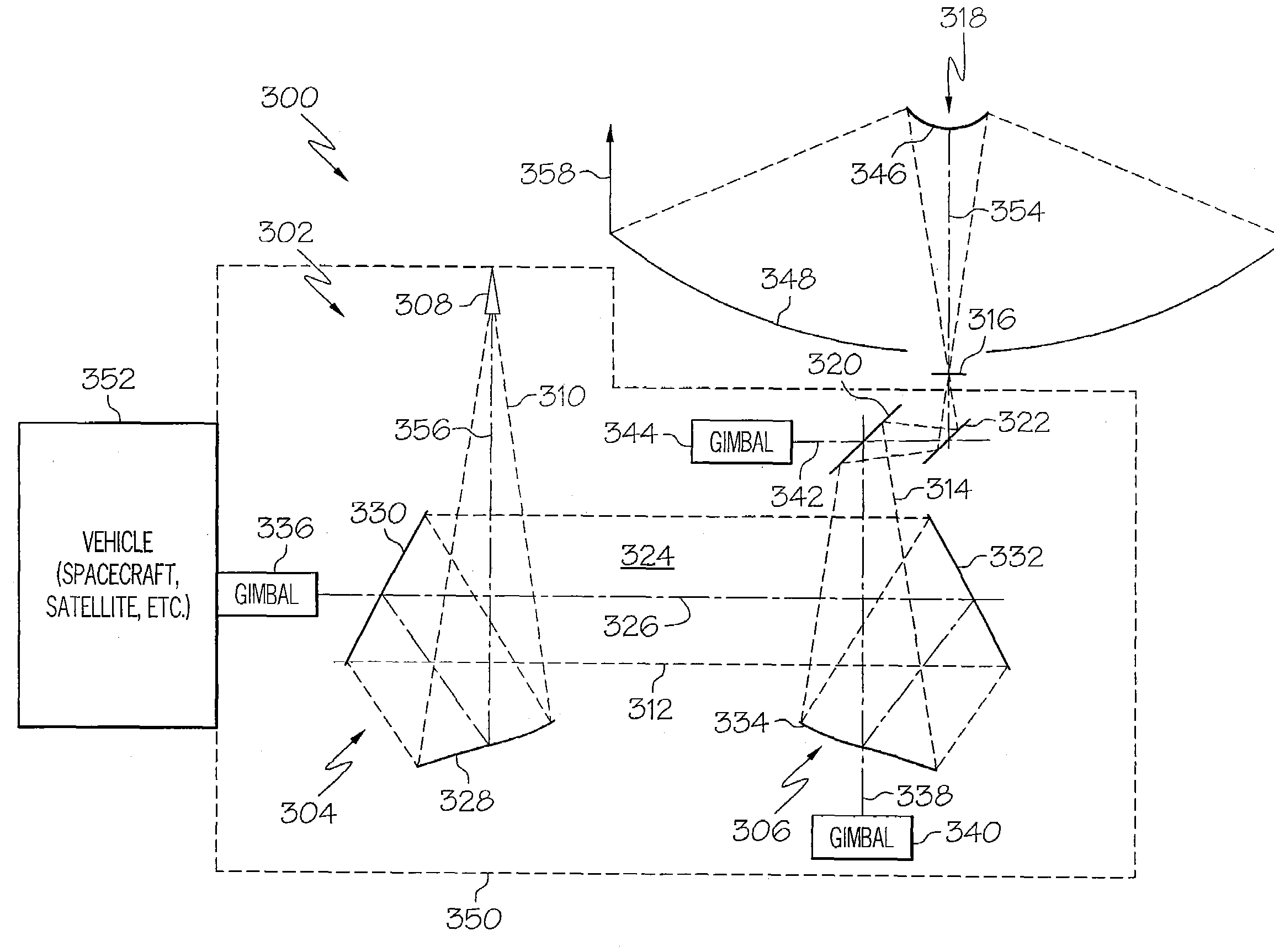
[0016]FIG. 3 is an illustration of an exemplary antenna system 300 including a beam waveguide 302 which includes a pair of dual offset reflector sets 304 and 306 that satisfy the Mizuguchi condition in accordance with an embodiment of the present invention. The system 300 may include a feed horn 308 that may radiate an electromagnetic or radio signal, beam or wave in the form of a spherical beam or wave 310 to the first set of dual offset reflectors 304 which collimates the beam 310. The collimated beam 312 then propagates to the second set of dual offset reflectors 306, which converts the beam back to a spherical wave 314, converging to a focus at a point 316, which may be the focus of a high gain reflector system 318, ant...


PUM


Abstract

A beam waveguide may include a first set of dual offset reflectors and a second set of dual offset reflectors. The first set of dual offset reflectors and the second set of dual offset reflectors may each include reflector geometries to produce a radiation pattern that is symmetric about a first axis between the first and second set of dual offset reflectors and to produce an axi-symmetric beam from the second set of dual offset reflectors that is unaffected by any rotation of the first and second set of dual offset reflectors relative to one another about the first axis.

Description

BACKGROUND OF THE INVENTION[0001]The present invention relates to waveguides, antennas and similar devices, and more particularly to a beam waveguide including a pair of dual offset reflector sets that satisfy the Mizuguchi condition and that may be associated with an antenna to send and receive signals.[0002]Satellite systems often require a high gain antenna such as a reflector antenna with a large aperture size to provide high data rate communications either between the satellite and a fixed location on the earth, such as a ground station, or between the satellite and a mobile user with a small, low gain terminal. Realizing such high gain antennas is often a complex interaction between competing needs associated with the spacecraft. For example, blockages by solar panels and other structures associated with the spacecraft, or other antennas should be avoided while mass and complexity are also minimized. In addition, the payload for the high gain antenna may require high power and...

Claims


Application Information

Patent Timeline
Patent Type & Authority Patents(United States)
IPC IPC(8): H01Q13/00H01Q3/00H01Q3/12
CPCH01Q1/288H01Q3/20H01Q19/191
Inventor BALDAUF, JOHN E.TZELEPIS, CHRIST P.WERNTZ, PAUL C.HIKIDO, TOM M.
Owner THE BOEING CO
Why Eureka
Try Eureka