Display method of X-ray CT image of maxillofacial area, X-ray CT apparatus and X-ray image display apparatus

a display method and maxillofacial area technology, applied in the direction of instruments, patient positioning for diagnostics, applications, etc., can solve the problems of difficult to understand the position and direction of the region at once, the slice plane of the obtained ct image is different from the view, and the operation has required a lot of tim

a display method and maxillofacial area technology, applied in the direction of instruments, patient positioning for diagnostics, applications, etc., can solve the problems of difficult to understand the position and direction of the region at once, the slice plane of the obtained ct image is different from the view, and the operation has required a lot of tim

US7787586B2Active Publication Date: 2010-08-31MORITA MFG CO LTD

Image

  • Display method of X-ray CT image of maxillofacial area, X-ray CT apparatus and X-ray image display apparatus
  • Display method of X-ray CT image of maxillofacial area, X-ray CT apparatus and X-ray image display apparatus
  • Display method of X-ray CT image of maxillofacial area, X-ray CT apparatus and X-ray image display apparatus

Examples


Embodiment Construction

[0067]Now, the embodiments of the present invention are explained referring to the drawings.

[0068]The embodiment of an X-ray CT apparatus for executing an X-ray computer tomography of a maxillofacial area of a patient is explained.

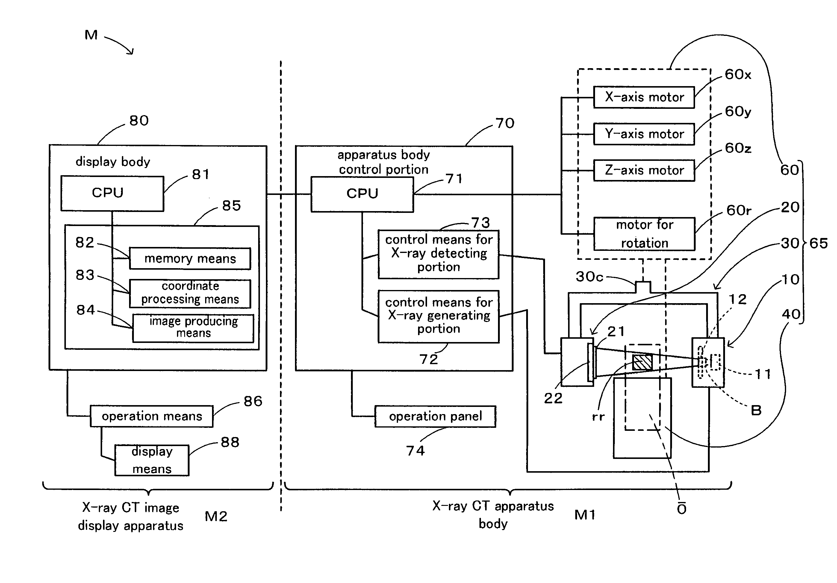
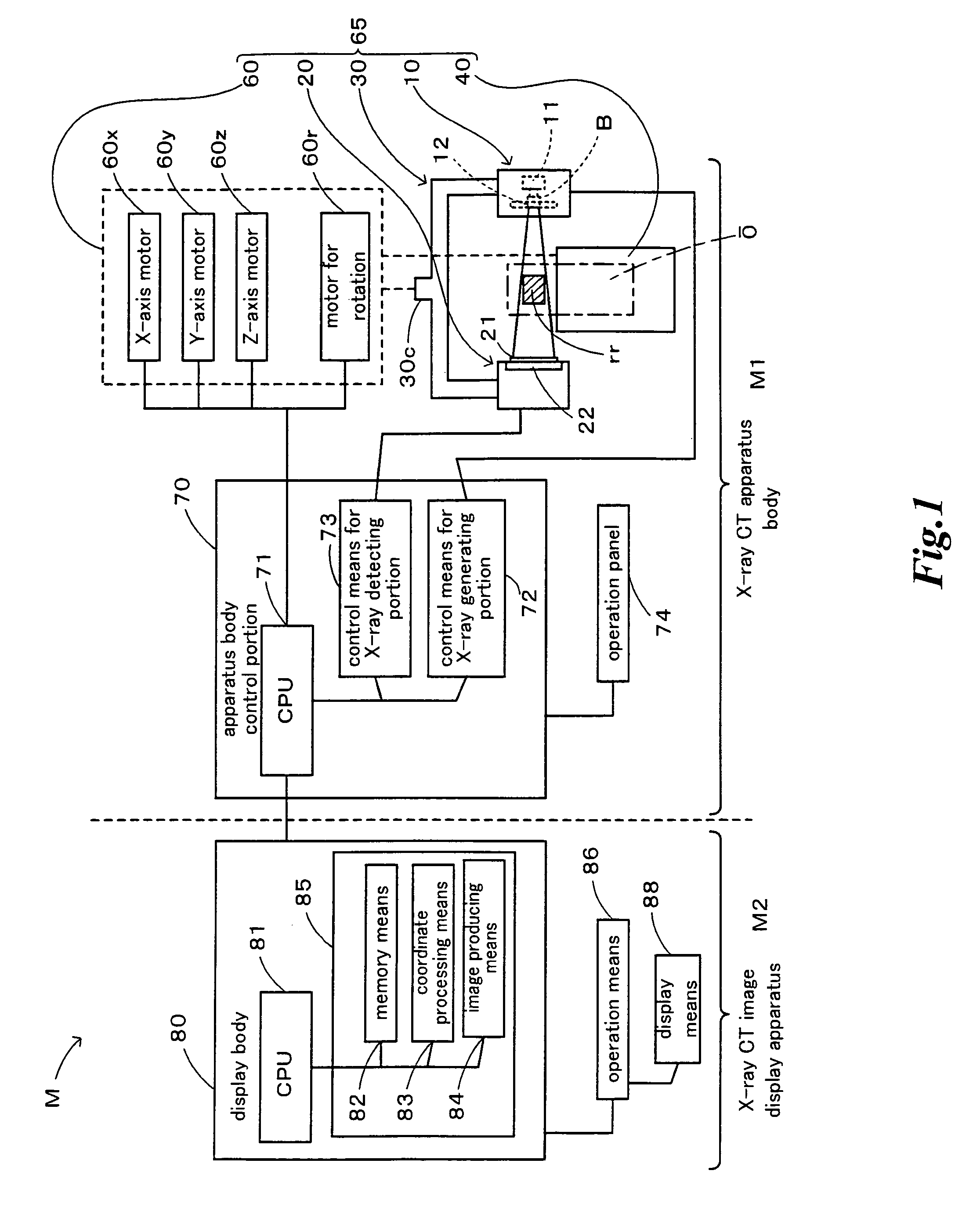
[0069]FIG. 1 is a block diagram showing a basic structure of an X-ray CT apparatus M. The X-ray CT apparatus M has an X-ray CT apparatus body M1 and an X-ray CT image display apparatus M2 and is designed to send and receive data via a communication cable.

[0070]The X-ray CT apparatus body M1 has a support means 30 for supporting an X-ray generating portion 10 and an X-ray detecting portion 20 facing each other, an object holding means 40 for holding a maxillofacial area being an object to be examined โ€œoโ€, a driving portion 60 for driving the support means 30 or the object holding means 40, and a main body control portion 70, to which an operation panel 74 is attached. The operation panel 74 may be used for designating an interested area โ€œrโ€ as mentioned lat...


PUM


Abstract

A method of displaying a standard observational X-ray CT image for diagnostics for use in an X-ray CT apparatus or an X-ray CT image display apparatus and an apparatus for displaying the same image are disclosed. The standard observational X-ray CT image can be displayed as a display image of at least one of an X-ray CT sectional image and a three-dimensional CT volume image depending on its purpose. The present method involves a step of designating the interested area with respect to the maxillofacial area of the object, a step of producing the standard observational X-ray CT image of the designated interested area, based on the dental arch reference information prepared in advance, and a step of displaying on a display means the standard observational X-ray CT image of the object thus produced.

Description

FIELD OF THE INVENTION[0001]The present invention relates to a sectional image display method, a display apparatus and a radiography apparatus wherein an X-ray computer tomography is executed for an object to be examined and a CT image of a desired interested area of the object is produced from the obtained CT data.PRIOR ART[0002]When a CT image of an area to be radiographed is produced from the CT data of a radiographed object, an optional slice plane may be settable in principle. However, it has been troublesome operation that a slice plane is set in a desirable direction relative to the interested area to be observed which is a part of the area to be radiographed and such operations have required much time.[0003]Similar prior art aiming to solve the problem is JP-A-2002-11000 which discloses a method in which CT images in a plurality of directions are cut out and prepared in advance from the three-dimensional data of a reconstructed area to be radiographed, a plurality of CT imag...

Claims


Application Information

Patent Timeline
31 Aug 2010
Publication
US7787586B2
IPC
A61B6/04; A61B6/14
CPC
A61B6/032; A61B6/14; A61B6/469
Inventors
YOSHIMURA, TAKAHIRO; SADAKANE, TOMOYUKI