Coordinate measuring machine

a technology of coordinate measuring machine and measuring axis, which is applied in the direction of program-controlled manipulators, instruments, and measurement apparatus components, can solve the problems of difficult engineering accuracy of polar machines, high cost, and difficult production of curvilinear parts with single axis devices, and achieves stable pitch error, high cost, and enhanced resolution

Inactive Publication Date: 2010-09-14
MAKEX LTD
View PDF13 Cites 35 Cited by
  • Summary
  • Abstract
  • Description
  • Claims
  • Application Information

AI Technical Summary

Benefits of technology

[0008]Embodiments of the invention can enable a parallel kinematic architecture to be exploited to produce a low cost measuring machine. Embodiments herein can also enable low build cost multi-axis linkages that are very repeatable and hysteresis free. In yet other aspects, embodiments herein can employ length encoders attached to stiff triangular section carbon fibre struts that will provide thermally stable and accurate displacement measurements. Measurement accuracy can also be improved using a handle that promotes a steady and predictable contact pressure between the object and the stylus tip according to other embodiments. Embodiments herein can also package the mechanical solution in a robust and compact style that enables it to be operated on the desk top at the user's convenience without special clean room or air conditioning requirements. Embodiments herein can also provide for software that presents a very intuitive and quick to use interface that also can extract more useful data from the part like contoured topography and surface roughness.
[0043]The struts may well have a pitch error in a pattern array of a printed circuit board encoder track. This pitch error is stable and can therefore be compensated for, if identified, by comparing a strut against an accurate absolute displacement transducer and holding the determined pitch error values in a look up table associated with each strut. By this means the individual axis absolute accuracy can approach that of the very best encoder without its probable high cost and stringent operating conditions.

Problems solved by technology

Increasingly, product designers with 3D CAD tools are producing curvilinear parts that are very difficult to measure with a single axis device, be it a ruler or a digital calliper gauge.
The former Cartesian machines have been refined and value engineered over many years but will always be expensive to build because the component technologies are expensive (sensitive probes, marble beds, air bearings, precise linear encoders, a very stiff frame etc).
The polar machines are difficult to engineer accurately because each degree of freedom is attached together in a series chain so that errors accumulate and the total stiffness and accuracy is the sum of all six linkage and encoder inaccuracies.
Also radial encoders that maintain micron accuracy at the end of a long lever are very expensive.
The inherent build and accuracy factors result in machines that have an entry level cost of over £10 k, often controlled by complex professional software that not only has a high capital cost but also takes a lot of training to use properly.
The demand for multi axis measurement is expected to grow rapidly, but to date there has not been a tool that is both affordable and easy to use for the small scale or discretionary user.

Method used


Image

  • Coordinate measuring machine
  • Coordinate measuring machine
  • Coordinate measuring machine

Examples


Embodiment Construction

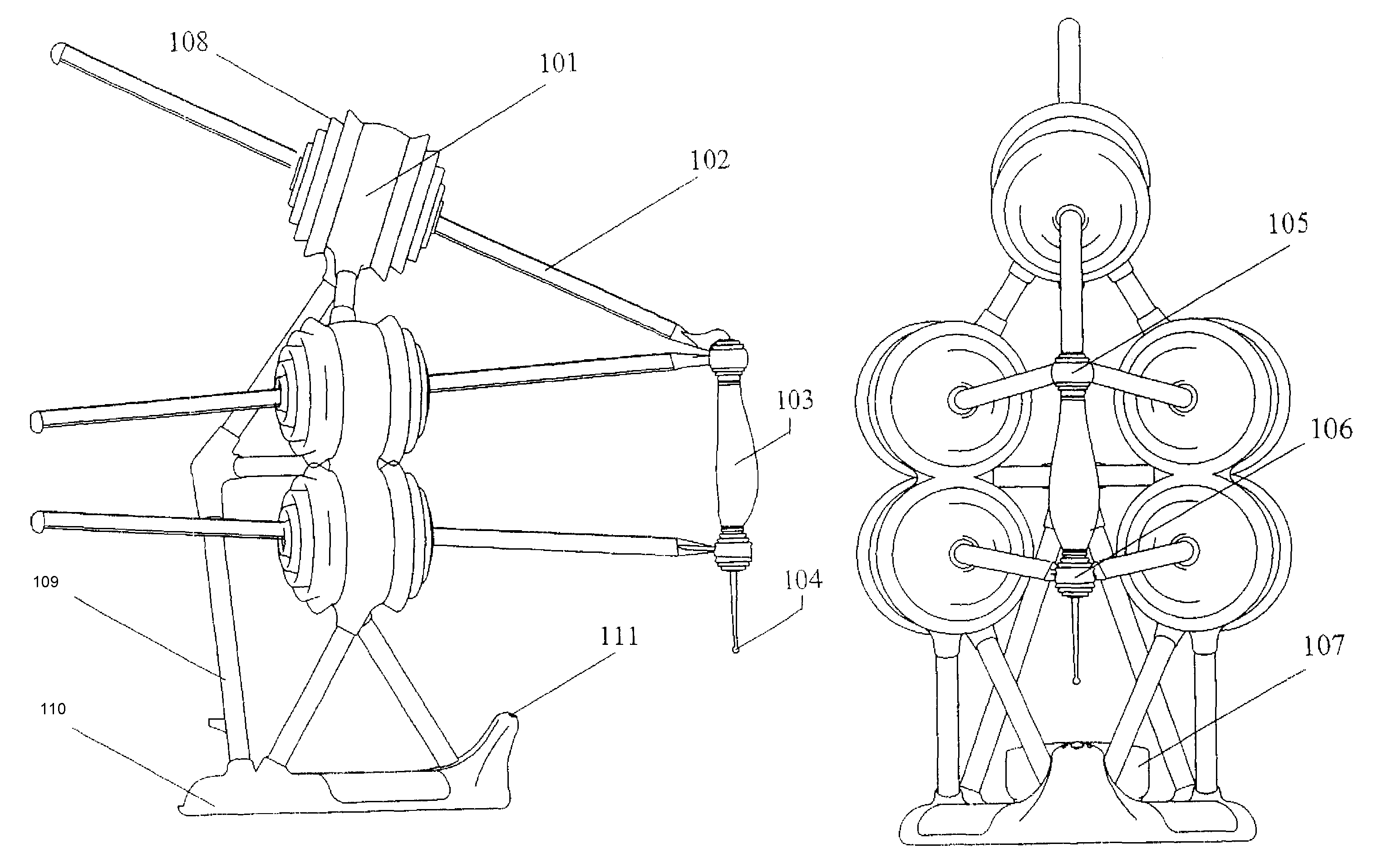
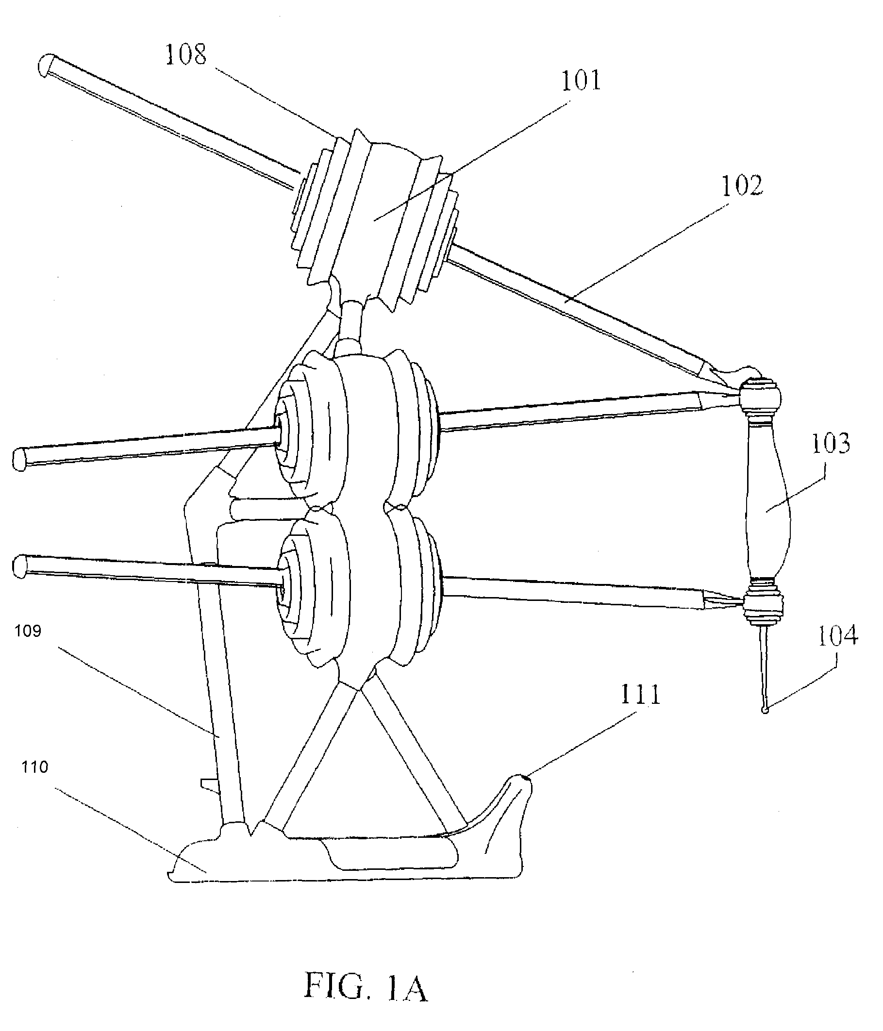
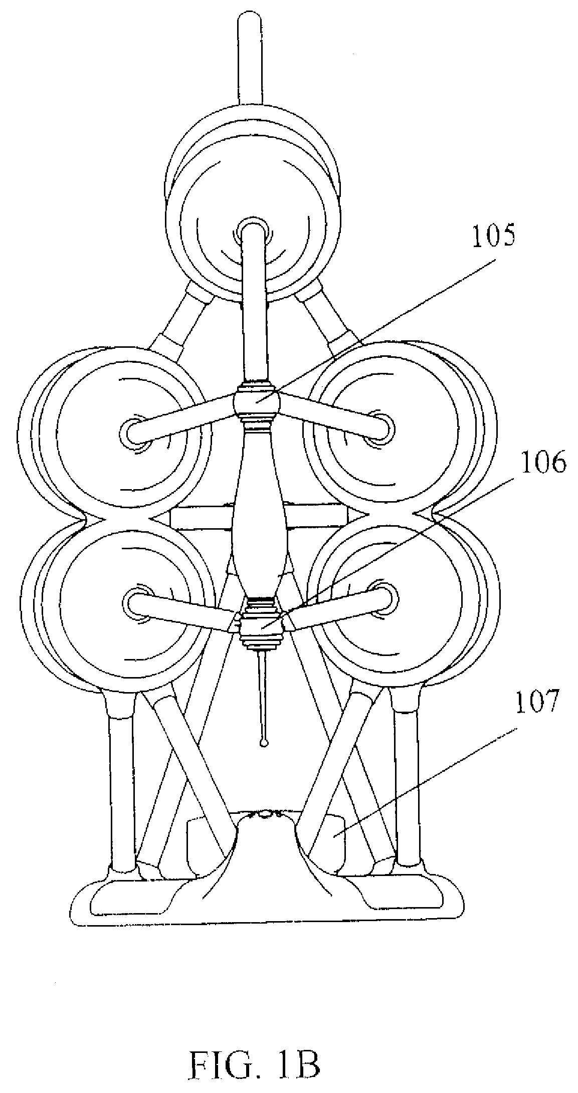
[0051]FIGS. 1a and 1b show side and front elevations respectively, of the device according to a preferred embodiment of the invention.

[0052]The truss framework that supports the nodes is arranged like a tetrahedron with a node 101 at its top vertex with other node pairs at the front bottom vertices. The back vertex and the lower front vertices are then connected like an octahedron with six struts 109 to the base moulding 110.

[0053]Five struts 102 then pass through the nodes 101 and connect as a tripod with its vertex at the quad-joint 105 and using this point as a new base point form another tripod with its vertex at the tri-joint 106, separated by the handle 103. The handle 103 extends downwards with a replaceable stylus tip 104, preferably with a hard ball at its end.

[0054]Elastomeric covers 108 connect the node frame to swivels on the struts on both sides of the nodes to prevent the ingress of contaminants.

[0055]At the front of the base 110 is an extension 111 that supports an in...


PUM


Abstract

A coordinate measuring machine operable to employ pentapod kinematics to determine the absolute position at a measuring point tip by measuring about five axes. The machine comprises a first, bifurcated linkage, a second, trifurcated linkage, and a plurality of elongate struts. First and second ones of the plurality of struts share the first linkage, third, fourth and fifth ones of the plurality of struts share the second linkage, and the first and second linkages are coupled via a handle. The first and second struts are preferably rotatably engaged to the first linkage, and the third, fourth and fifth struts may be rotatably engaged to the second linkage. First through fifth nodes may be provided, each node being slidably engaged to a corresponding one of the first through fifth struts. The nodes may comprise means for measuring the displacement of the corresponding strut relative to the node.

Description

FIELD OF THE INVENTION[0001]The invention relates to a device for determining the geometrical dimensions of an object by a process of surface probing including digitising a path along an object rather than just a point. By articulation about six degrees of freedom (6 DOF), a user may be enabled to access more of an object's surface without having to move the object or fit a new stylus to the probe. The device uses a novel form of parallel kinematic architecture to enable spatial data to be measured without the usual cost and complexity. It also employs novel linkages to ensure better accuracy and repeatability than would usually be possible at such low costs.BACKGROUND OF THE INVENTION[0002]Increasingly, product designers with 3D CAD tools are producing curvilinear parts that are very difficult to measure with a single axis device, be it a ruler or a digital calliper gauge.[0003]Coordinate Measuring Machines (CMMs) are a common tool for the metrology of 3D objects. They tend to eith...

Claims


Application Information

Patent Timeline
Patent Type & Authority Patents(United States)
IPC IPC(8): G01B5/004G01B5/008
CPCG01B5/008B25J9/16F16C11/06G01B21/04G01B5/0004G01B21/045G01D11/30
Inventor BAILEY, RALPH-PETER S.
Owner MAKEX LTD
Why Eureka
Try Eureka