Static mixer and exhaust gas treatment device

a technology of exhaust gas treatment and mixer, which is applied in the direction of machine/engine, combustion-air/fuel-air treatment, and separation processes, etc., can solve the problems of certain increase in pressure, and achieve the effects of low flow resistance, intense mixing effect and/or vaporization effect, and low cos

Inactive Publication Date: 2010-09-14
EBERSPACHER EXHAUST TECH GMBH & CO KG
View PDF24 Cites 103 Cited by
  • Summary
  • Abstract
  • Description
  • Claims
  • Application Information

AI Technical Summary

Benefits of technology

[0007]According to an aspect of the invention, there is provided a mixer and an exhaust gas treatment device having an inexpensive design and a comparatively intense mixing effect and / or vaporization effect with a comparatively low flow resistance.
[0008]The invention is based on the general idea of implementing the mixer with the help of a corrugated sheeting of material that is stacked in several layers across the direction of flow such that cells through which the flow can pass in the direct flow direction are formed between neighboring layers. The sheeting material is equipped with baffles that are arranged with an inclination with respect to the direction of flow on the outgoing flow end of several cells, preferably all cells. The corrugated sheeting material can be manufactured especially inexpensively. At the same time, the mixers have a simple design so that the mixer can be implemented inexpensively. In addition, the individual cells with the baffles assigned in a predetermined manner ensure a targeted and thus intense vaporization effect and / or mixing effect. At the same time the pressure drop in flow through this mixer can be kept comparatively small due to the selected design with the flow-carrying cells. Finally, this mixer has a relatively short design in the direction of flow.
[0009]In an exemplary embodiment, the corrugated form of the sheeting material is uniformly selected so that the corrugations that occur have the same wavelength and the same amplitude. This simplifies inexpensive production of the sheeting material.
[0010]In another embodiment, the sheeting material is arranged so that it is offset by one half wavelength across the direction of flow in each layer in comparison with the sheeting material of the next neighboring layer. Subsequently, the hills of the corrugations of one layer are in contact with the valleys of the corrugations of the neighboring layer, whereby the cells are formed between these contact points. In this configuration, the cells have maximum flow cross sections, which is advantageous with regard to a low flow resistance.
[0012]Yet another embodiment has the sheeting material which extends without interruption over at least two neighboring layers, and may also extend over all layers. The sheeting material is then folded or bent over into the neighboring layer on the lateral ends of the respective layer. A wall structure constructed with the help of the layered sheeting material can thus be manufactured from just a single component, so that production of this wall structure and therefore of the mixer is extremely inexpensive. In particular it is not necessary to attach the sheeting material separately to the pipe or to a ring encompassing the wall structure in the circumferential direction in each layer.
[0013]According to another embodiment, the baffles may be shaped integrally on the sheeting material in particular, dimensioned and oriented with respect to the direction of flow so that they seal and / or overlap the cells in the direction of flow at least 80% or at least 90% or at least 95% or 100% in a completely lightproof manner. Due to this design, it is possible to achieve an intense mixing and / or complete evaporation. For example, this ensures that liquid droplets sprayed upstream from the mixer will strike the baffles with a very high probability and thus cannot flow through the mixer unhindered. As soon as the liquid adheres to the baffles, it is exposed to the exhaust flow and its vaporizing effect.

Problems solved by technology

Since static mixers work with deflection of flow, they necessarily result in a certain increase in pressure.
Furthermore, another factor to be taken into account for applications in motor vehicles is that usually there is only a small installation space for accommodating such a mixer in the exhaust systems used there.

Method used


Image

  • Static mixer and exhaust gas treatment device
  • Static mixer and exhaust gas treatment device
  • Static mixer and exhaust gas treatment device

Examples


Embodiment Construction

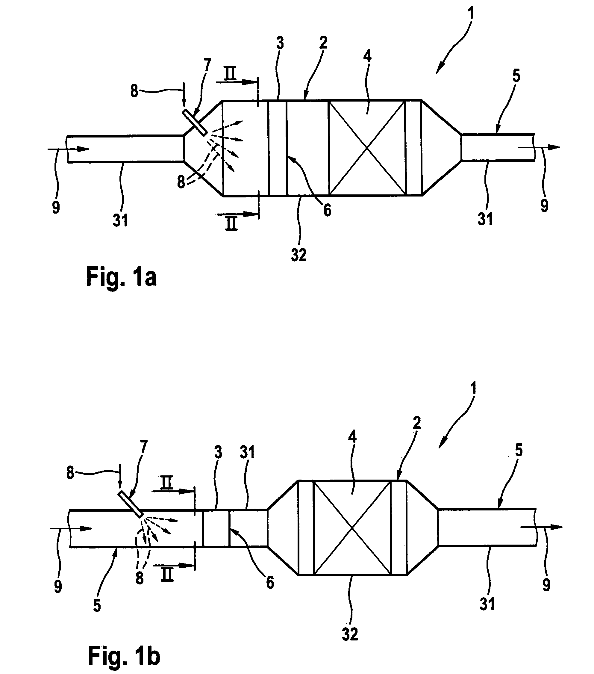
[0026]Referring to FIG. 1a, an exhaust gas treatment device 1 has a housing 2 with a tubular body 32 that forms a jacket of the housing 2. At least one exhaust gas treatment insert 4 is arranged in the tubular body 32. The exhaust gas treatment device 1 is tied into an exhaust system 5 of an internal combustion engine (not shown). The exhaust gas treatment device 1 may be a muffler, a particulate filter, a catalytic converter or any desired combination of the aforementioned devices. Accordingly, the exhaust gas treatment insert 4 may be, for example, a catalytic converter element or a particulate filter element. Likewise, it may be a muffler arrangement.

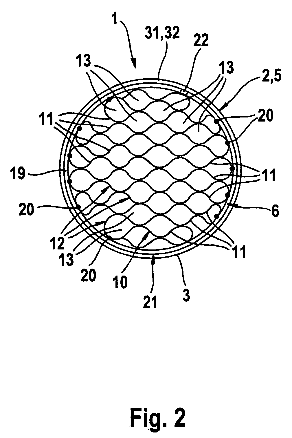
[0027]Upstream from the exhaust gas treatment insert 4 a static mixer 6 is installed in the tubular body 32 and is explained in greater detail below with reference to FIGS. 2 through 9. With the help of a spray nozzle 7 arranged upstream from the mixer 6, a liquid, represented by arrows 8, can be sprayed into the exhaust gas flow, re...


PUM

PropertyMeasurementUnit
half-wavelengthaaaaaaaaaa
half-wavelengthsaaaaaaaaaa
wavelengthaaaaaaaaaa

Abstract

The invention relates to a static mixer for an exhaust system of an internal combustion engine. The mixer has a wall structure that is arranged across the directional of flow in a pipe and has several layers of a corrugated sheeting material laying across one another in the direction of flow. The cells through which the flow can pass in the direction of flow are provided between the sheeting material of neighboring layers. The sheeting material has baffles for all or several of the cells. The baffles are arranged on the sheeting material so that they are arranged on their outgoing flow side in the case of said cells and extend in the direction of flow and across it.

Description

FIELD OF THE INVENTION[0001]The present invention relates to a static mixer for an exhaust system of an internal combustion engine. The invention also relates to an exhaust gas treatment device for an exhaust system of an internal combustion engine equipped with such a mixer.BACKGROUND OF THE INVENTION[0002]In internal combustion engines, mixers of the aforementioned type may be used in their exhaust system, for example, if a gas or a liquid is to be admixed with the exhaust gas. The mixing should be especially intense so as to be able to produce the most homogeneous possible gas mixture and / or to achieve effective evaporation of the liquid introduced and to achieve thorough mixing of the vaporized liquid with the exhaust gas. At the same time, the mixer should not produce an excessively great pressure increase in the exhaust system. Since static mixers work with deflection of flow, they necessarily result in a certain increase in pressure. Therefore, there has been a demand for eff...

Claims


Application Information

Patent Timeline
Patent Type & Authority Patents(United States)
IPC IPC(8): F01N1/00F01N13/08B01F23/10
CPCB01F3/04049B01F5/0451B01F5/0618B01F5/0643F01N3/0253F01N3/2066F01N2240/20F01N2330/38F01N2470/10F01N2610/02F01N2610/03F01N2610/102Y02T10/24Y02A50/20Y02T10/12B01F23/2132B01F25/3131B01F25/4316B01F25/4322
Inventor WIRTH, GEORGNEUMANN, FELIX
Owner EBERSPACHER EXHAUST TECH GMBH & CO KG
Why Eureka
Try Eureka