Bumper fixture, and bumper mounting structure

a technology for bumpers and mounting structures, which is applied to bumpers, vehicle components, vehicular safety arrangments, etc., can solve the problems of inability to solidly screw the end portion of the bumper on the auto body, inability to form mounting holes, and inability to fix the bumper to the body solidly, so as to improve the retention capacity (mounting strength) of the bumper relative to the auto body, simple structure, and the effect of improving the mounting strength

Inactive Publication Date: 2010-09-14
NIFCO INC +1
View PDF21 Cites 49 Cited by
  • Summary
  • Abstract
  • Description
  • Claims
  • Application Information

AI Technical Summary

Benefits of technology

[0011]On the other hand, since the mounting portion can be elastically deformed by the load with more than the predetermined load, even if the bumper is expanded and contracted according to temperature changes, the mounting portion is deformed and absorbs the expansion and contraction of the bumper, so that the mounting portion can cope with size changes of the bumper. Therefore, even if the bumper changes size in a longitudinal direction due to temperature changes, a matching surface between the bumper and the auto body can be retained in one surface, thereby maintaining the appearance of the bumper.
[0013]As a result, based on the locked portion and the locking portion, retention capacity (mounting strength) of the bumper relative to the auto body can be improved. At the same time, a stretching force of the bumper may be acted on the mounting portion without being controlled by the locked relationship between the locked portion and the locking portion. Furthermore, the internal contraction force can be let escape by an elastic deformation of the mounting portion. Consequently, while dependent upon size changes of the bumper due to temperature changes, the mounting strength of the bumper relative to the auto body may be improved.
[0014]According to the third aspect of the invention, because the mounting hole is formed in a risen plate portion that rises independently relative to other component portions, the extended-directional outer end wall of the bumper may be mounted on the bumper fixture using the mounting hole. Accordingly, the risen plate portion may be risen and lowered (elastic deformation) by the load with more than the predetermined load. As a result, the mounting portion of the bumper fixture may comprise a simple structure.
[0015]According to the fourth aspect of the invention, the mounting portion which can be elastically deformed by the load with more than the predetermined load is formed on one of the extended-directional ends of said bumper fixture, and the extended-directional outer end wall of said bumper is mounted on said mounting portion, so that the bumper fixture according to said first aspect can solidly mount the extended-directional end portion of the bumper on the auto body, and also cope with the size changes of the bumper according to the temperature changes.
[0016]According to the invention described in the fifth aspect, either the locked portion or the locking portion is provided on one side of the width direction of the bumper fixture, and another side of either the locked portion or the locking portion is provided on one side of the width direction of the bumper. The locked state between either the locked portion or locking portion and another side of either the locked portion or locking portion, is set to slide relatively in the extended direction of the bumper. As a result, the bumper fixture according to the second aspect can improve the mounting strength of the bumper relative to the auto body while coping with the size changes of the bumper due to the temperature changes.
[0017]The mounting portion of the bumper fixture in the sixth aspect comprises a mounting hole formed in the risen plate portion rising independently relative to other component parts of the bumper fixture. A mounting hole formed on the extended-directional outer end wall of the bumper corresponds to the bumper fixture mounting hole and a fastener is mounted on the mounting hole of the risen plate portion and on the mounting hole of the extended-directional outer end wall of the bumper. The risen plate portion of the bumper fixture and the extended-directional outer end wall of the bumper are integrated. Therefore, the bumper fixture according to the third aspect may allow the extended-directional end portion of the bumper to solidly mount to the auto body, notwithstanding any size changes of the bumper due to temperature changes.

Problems solved by technology

However, in a structure wherein the extended-directional end portion of the bumper is screwed shut on the auto body by using a mounting hole, when the bumper is expanded and contracted due to temperature changes, the structure cannot cope with the changes in size of the bumper in extended direction, with a result that a matching surface between the bumper and the auto body cannot be retained in one surface, and thereby adversely affecting the appearance of the bumper.
Since the seal material exists on the upper wall of the auto body depression wherein the bumper is attached, the mounting hole cannot be formed.
As a result the end portion of the bumper cannot be solidly screwed shut on the auto body.

Method used


Image

  • Bumper fixture, and bumper mounting structure
  • Bumper fixture, and bumper mounting structure
  • Bumper fixture, and bumper mounting structure

Examples


Embodiment Construction

[0029]Hereinafter, preferred embodiments of the present invention will be explained with reference to the attached drawings.

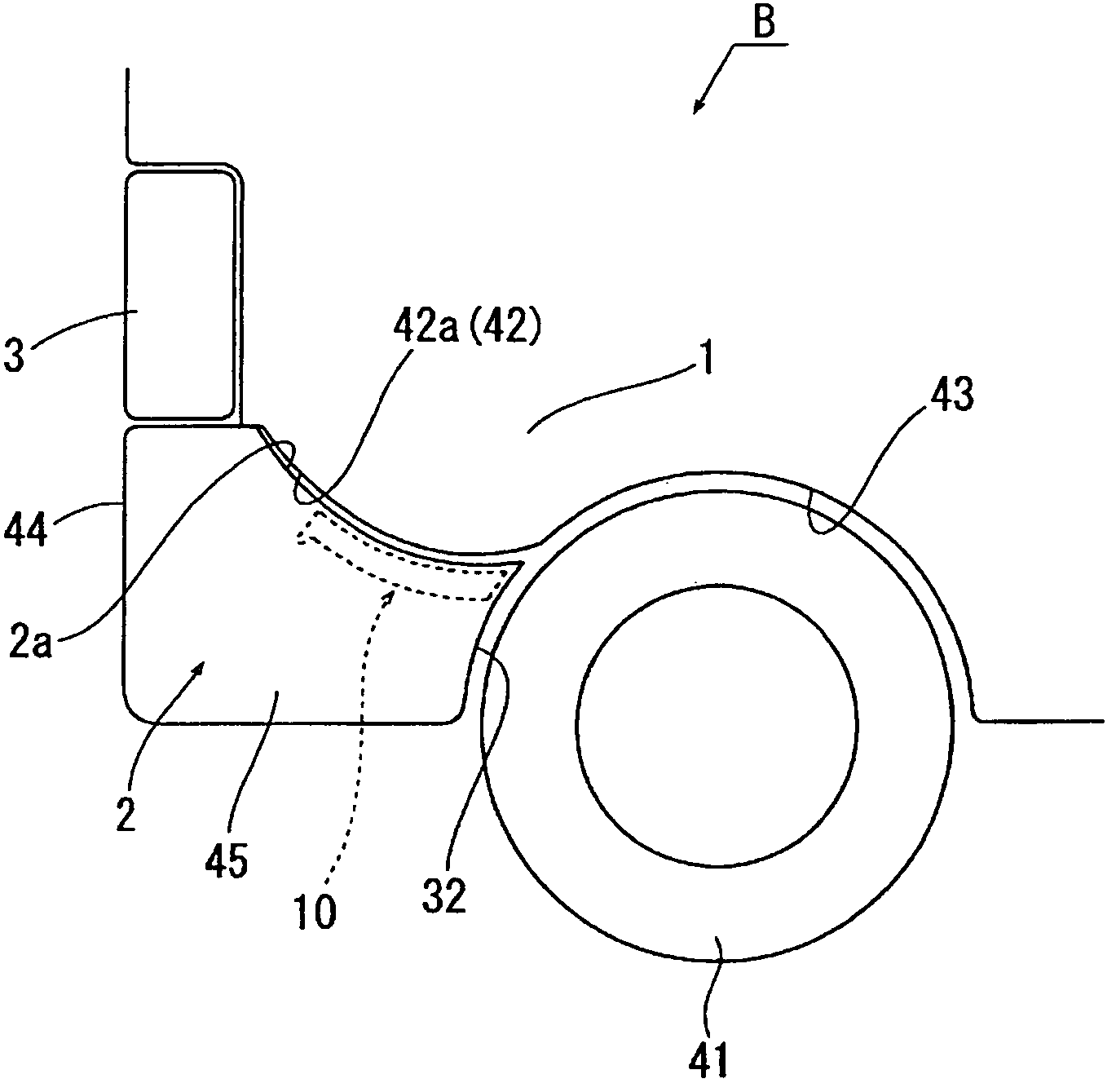
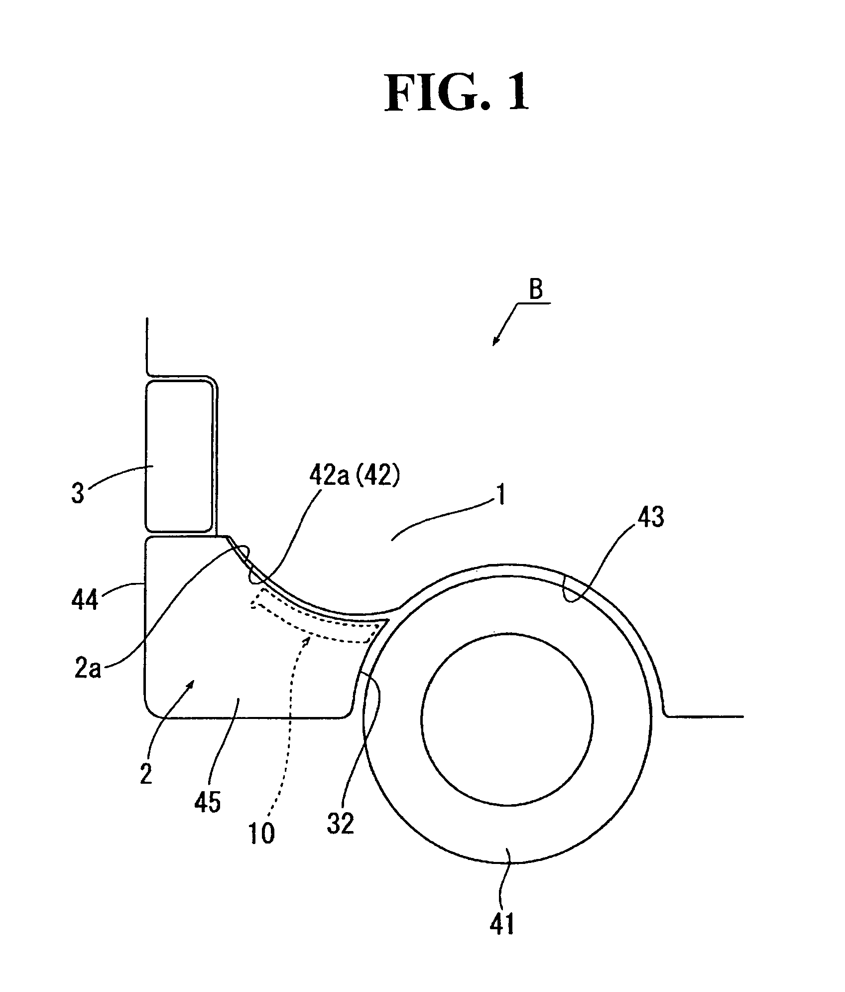
[0030]In FIG. 1, the reference alphabet B represents an auto body; a rear bumper 2 is provided on the lower portion of the back side of the auto body B; and a rear combination lamp 3 is provided on the upper side of the rear bumper 2.

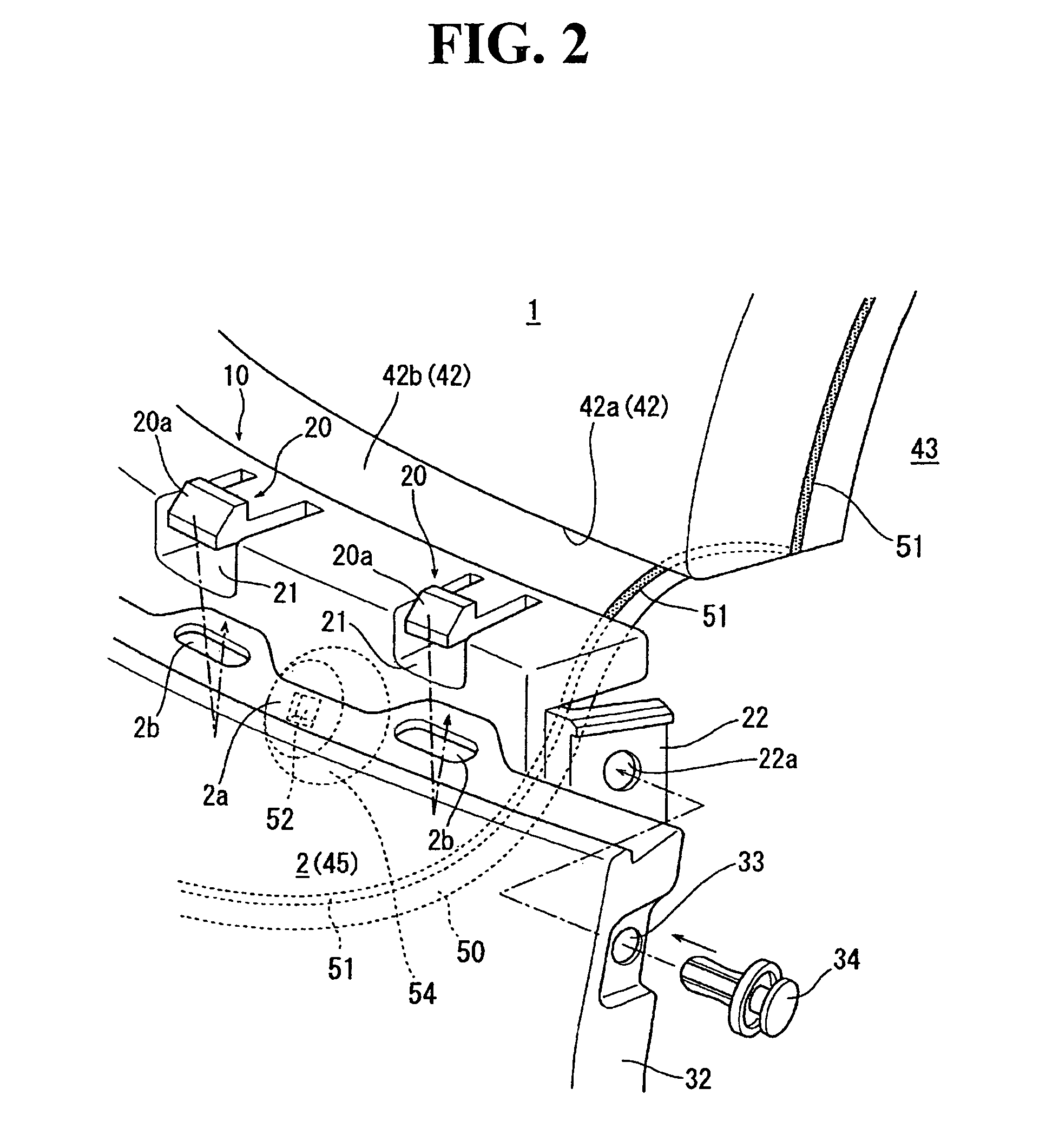
[0031]As shown in FIGS. 1 and 2, on both side walls 1 of said auto body B, a depression 42 depressed to the inner side of an auto width direction is formed in the back side of the auto body further than a back wheel 41. The depression 42 includes a depression upper wall 42a and a depression longitudinal wall 42b hanging from the depression upper wall 42a. The depression upper wall 42a becomes a projection toward the lower side and is curved in such a way as to gradually drop downward as the auto body moves forward (refer to FIG. 1). The inside of the depression 42 opens not only to the outside of the auto width direction but also t...


PUM


Abstract

A bumper fixture is interposed between an extended-directional end portion of a bumper and an auto body as to extend the extended-directional end portion of the bumper mounted on the auto body to form a part of a wheel house. The bumper fixture includes a mounting portion mountable to an extended-directional outer end wall of the bumper on one extended-directional end portion of the bumper, and the mounting portion is elastically deformable by a greater than predetermined load. A bumper mounting structure includes the bumper fixture such that an extended directional outer end wall of the bumper is mounted on the mounting portion.

Description

BACKGROUND OF THE INVENTION AND RELATED ART STATEMENT[0001]The present invention relates to a bumper fixture and a bumper mounting structure.[0002]Japanese Patent Publication No. 2003-191807 discloses a bumper mounting structure for an automobile wherein the bumper is fixed to an auto body by mounting a bumper fixture (clip) on the auto body. More specifically, the bumper fixture is mounted on the longitudinal wall of an auto body depression and an upper side flange portion of a bumper is mounted on the bumper fixture. However, there is the case wherein the extended-directional end portion of the bumper comprises a part of a wheel house. In order to prevent the extended-directional end portion of the bumper from easily coming off the auto body, Japanese Utility Model Publication No. S63-128157 discloses a mounting hole formed on an upper surface of the auto body depression to which the bumper is attached, and using the mounting hole, the extended-directional end portion of the bumpe...

Claims


Application Information

Patent Timeline
Patent Type & Authority Patents(United States)
IPC IPC(8): B60R19/24
CPCB60R19/24B60R2019/247
Inventor MATSUI, TAKEOOOKI, KENJIAIZAWA, MAKOTOMASAOKA, YUJI
Owner NIFCO INC
Why Eureka
Try Eureka