Linear module

a technology of linear modules and modules, applied in the direction of linear bearings, shafts and bearings, bearings, etc., can solve the problems of rigidity and and achieve the effect of improving the visual appearance of the table parts and not only the stability of the table parts

Inactive Publication Date: 2010-09-14
ROBERT BOSCH GMBH
View PDF31 Cites 5 Cited by
  • Summary
  • Abstract
  • Description
  • Claims
  • Application Information

AI Technical Summary

Benefits of technology

[0005]This object is attained according to the invention by means of a linear module of the type mentioned at the beginning in which the length of the table part measured in the direction of the longitudinal axis is greater than that of the linear guide device and in which at least one end cap is accommodated in a recess of the table part; the recess is open toward the underside of the table part and is delimited by the top surface of the table part, by at least one side wall of the table part, and by the main part of the linear guide device. The at least one side wall of the table part in this instance extends essentially orthogonal to the top surface of the table part, but essentially parallel to the longitudinal axis of the rail. In this way, the side wall of the recess contributes not only to the stability of the table part, but also improves the visual appearance of the table part and therefore of the entire linear module.
[0006]According to the invention, one of the two end caps can in fact be mounted from an end surface of the table part. For the other end cap, however, a recess is let into the table part from the underside of the table part and this other end cap can be inserted into this recess from the underside of the table part. The provision of the recess, whose size is adapted to that of the end cap, allows for the least possible weakening of the table part. It is naturally also conceivable in principal for both end caps to be situated in corresponding recesses.
[0015]In order to have sufficient room in the table part to accommodate the heads of threaded bolts or similar fastening elements for fastening the adapter to the table part, the adapter can be provided with a recess and the table part can have a bridge piece that is embodied to fit this recess. In addition, this bridge piece can contribute to the stability and rigidity of the table part.
[0016]In a modification of the invention, the adapter can be embodied with a lubrication bore for conveying lubricant between the end cap and the main part. For example, it is possible to convey lubricant from a lubricant supply point to an end surface of the table, through the end cap situated there, a corresponding conduit in the main part of the linear guide device, and the lubricant bore of the adapter to the end cap situated in the recess in order to be able to provide a sufficient lubrication of the roller elements in the region of this end cap as well.

Problems solved by technology

The problem of the stability and rigidity of the table part comes into play particularly when accompanied by a simultaneous requirement to embody the table part with the lowest possible profile.

Method used


Image

  • Linear module
  • Linear module
  • Linear module

Examples


Embodiment Construction

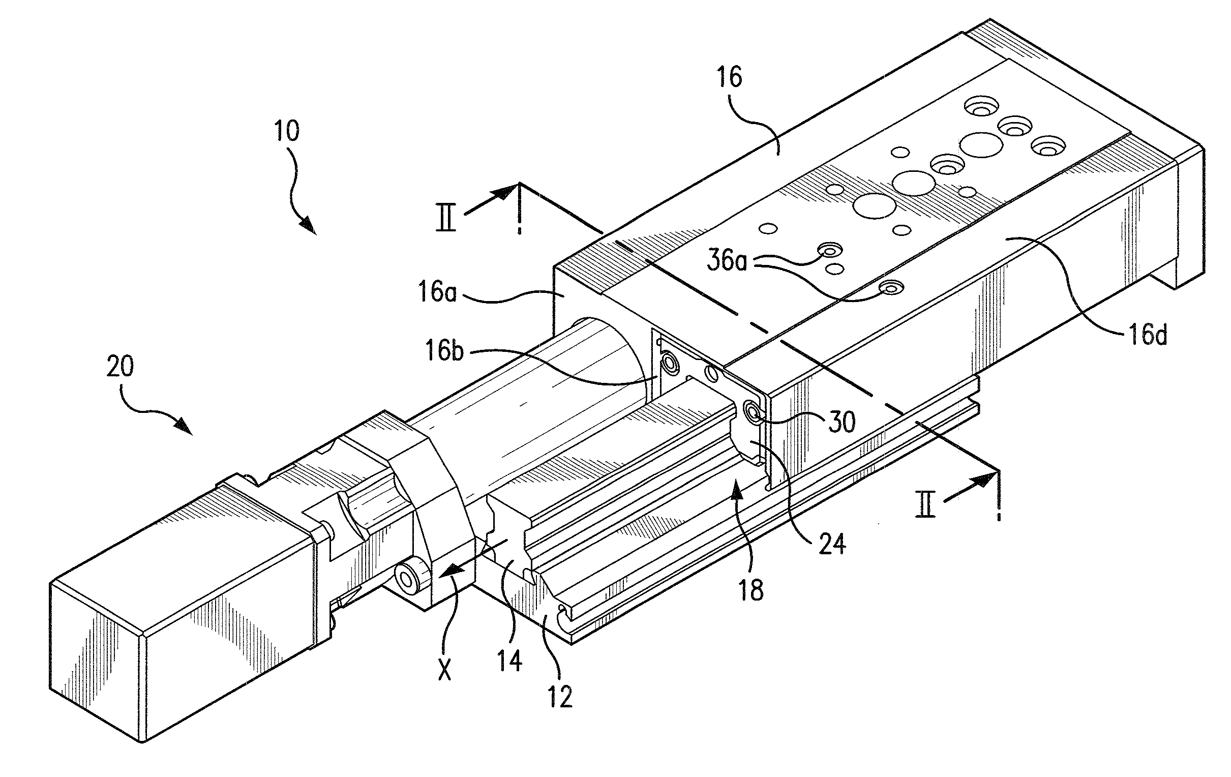
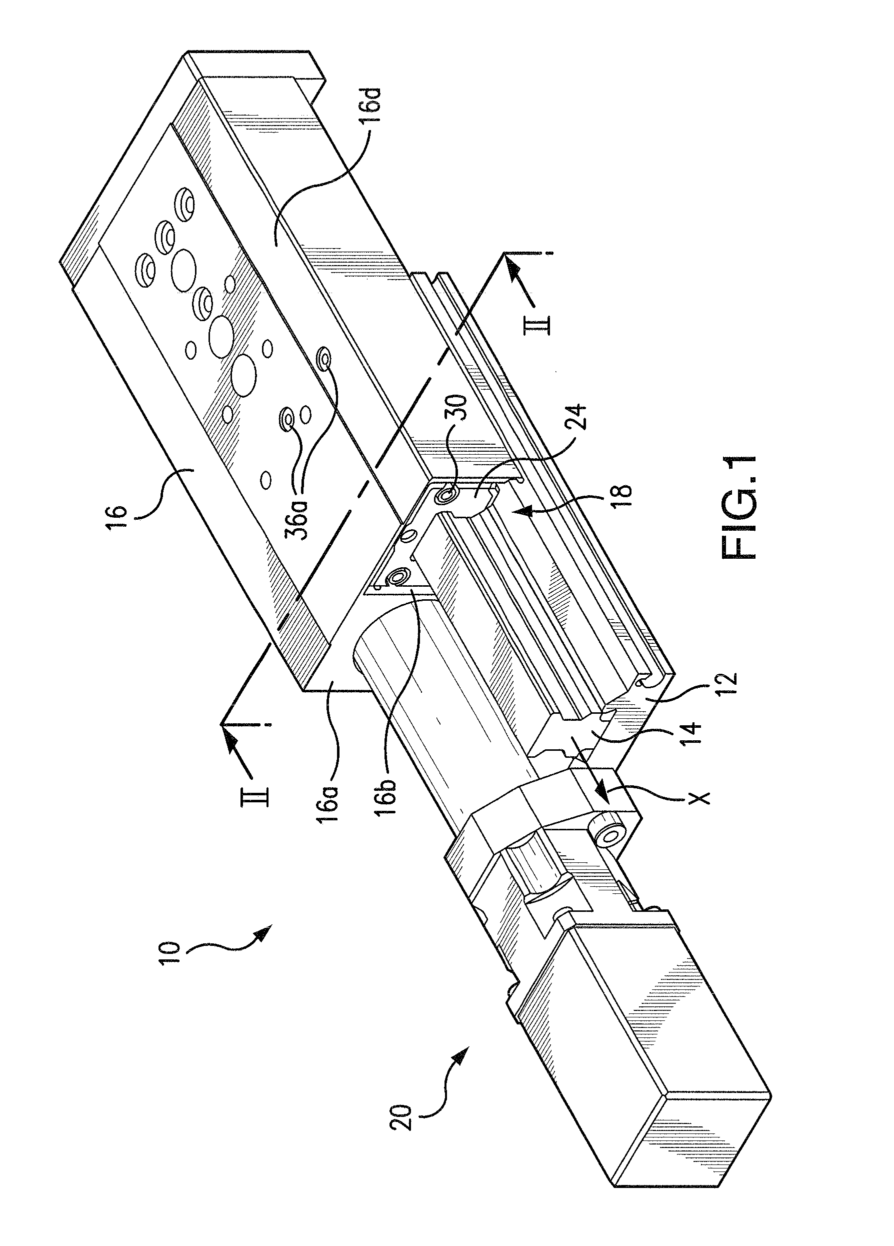
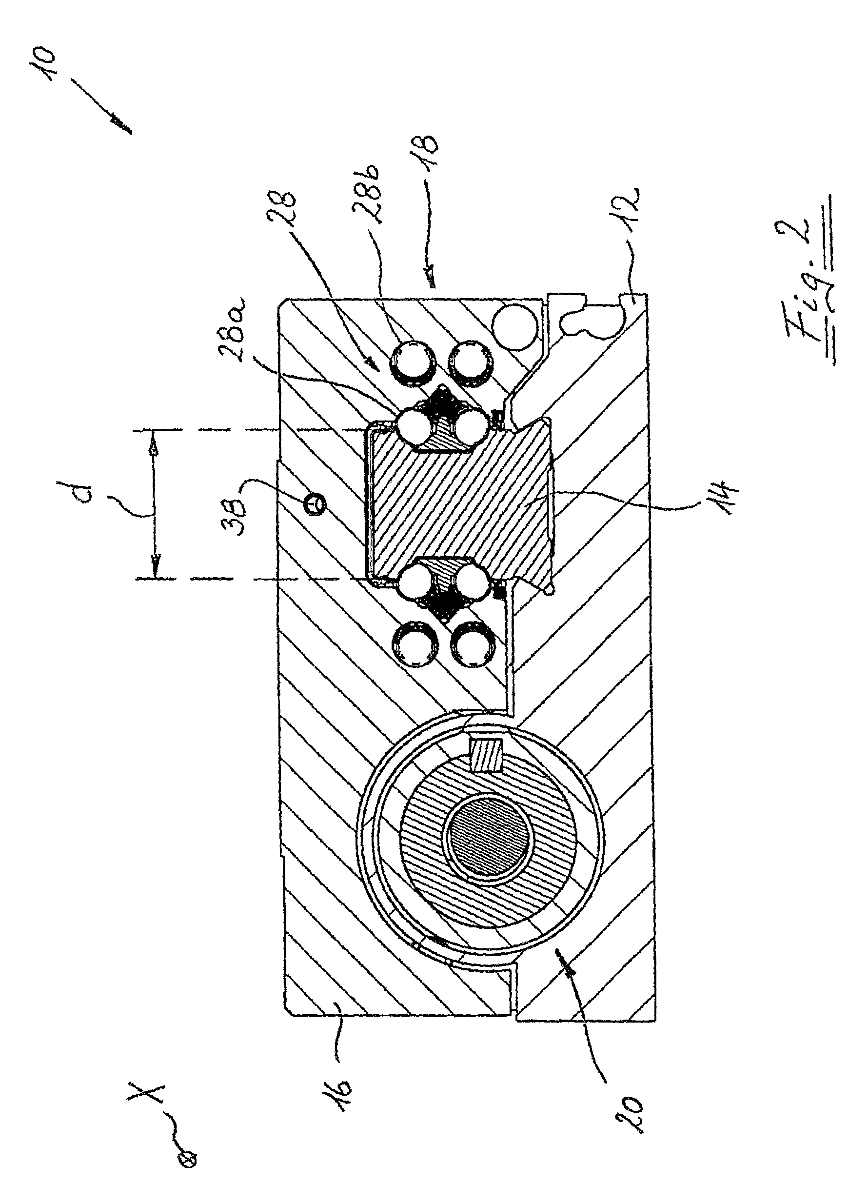
[0025]In FIGS. 1 and 2, the linear module according to the invention is labeled as a whole with the reference numeral 10. It includes a rail 14 mounted on a baseplate 12, extending in a longitudinal direction X. It also includes a table part 16, that a linear guide device 18 guides on the rail 14 in a movable fashion in its longitudinal direction X. The table part 16 is driven in relation to the rail 14 by a spindle drive 20, whose design is intrinsically known and therefore does not need to be explained in greater detail here.

[0026]As is known, the linear guide device 18 contains a main part 22 (also see FIGS. 3 and 4), which is embodied as integral to the table part 16, and two end caps 24 (also see FIG. 4) and 26 (see FIG. 5), which are attached to the end surfaces of the main part 22 extending essentially orthogonal to the longitudinal direction X. In the exemplary embodiment shown, the linear guide device 18 has a total of four roller element circuits 28, each with a load-beari...


PUM

PropertyMeasurementUnit
lengthaaaaaaaaaa
widthaaaaaaaaaa
rigidityaaaaaaaaaa

Abstract

A linear module has a rail with a longitudinal axis, a table part, and at least one linear guide device; the at least one linear guide device has a main part embodied so that it is integrally joined to the table part, two end caps, and at least one endless roller element circuit. The length of the table part measured in the direction of the longitudinal axis is greater than that of the linear guide device and at least one end cap is accommodated in a recess of the table part; the recess is open toward the underside of the table part and is delimited by the top surface of the table part, by at least one side wall of the table part, and by the main part of the linear guide device.

Description

CROSS-REFERENCE TO A RELATED APPLICATION[0001]The invention described and claimed hereinbelow is also described in German Patent Application DE 10 2007 006 248.8 filed on Feb. 8, 2007. This German Patent Application, whose subject matter is incorporated here by reference, provides the basis for a claim of priority of invention under 35 U.S.C. 119(a)-(d).BACKGROUND OF THE INVENTIONField of Invention[0002]The invention relates to a linear module including a rail with a longitudinal axis, a table part, and at least one linear guide device by means of which the table part is movably guided on the rail along its longitudinal axis; the at least one linear guide device has a main part embodied as integrally joined to the table part, two end caps, and at least one endless roller element circuit; the roller element circuit has a load-bearing roller element channel section, a return channel section that is at least partly accommodated in the main part, and two deflecting channel sections that...

Claims


Application Information

Patent Timeline
Patent Type & Authority Patents(United States)
IPC IPC(8): F16C29/06
CPCF16C29/0645F16C2322/39
Inventor KELLER, BERNHARDPFISTER, STEFFEN
Owner ROBERT BOSCH GMBH
Why Eureka
Try Eureka