Electrical connectors and methods of manufacturing and using same

a technology of electrical connectors and connectors, which is applied in the direction of electrical connection bases, coupling device connections, conductor screwing into other directions, etc., can solve the problems of not always easy to determine quality and permanence, and reducing the integrity and effectiveness of crimp-connection devices. , to achieve the effect of reliable and secure electrical connection

Active Publication Date: 2010-09-14
MELNI
View PDF44 Cites 14 Cited by
  • Summary
  • Abstract
  • Description
  • Claims
  • Application Information

AI Technical Summary

Benefits of technology

[0016]In each of the preferred embodiment groups, the conductive spiral(s) are sized to be, when relaxed in the larger-diameter configuration, significantly larger than the combined diameter of the wire(s) / element(s) being inserted into the conductive spiral. Only upon twisting of one end of the conductive spiral(s) relative to their other end(s) will the spiral(s) reduce in diameter to an extent that the spiral(s) will exert substantial force on the wire(s) / element(s) inside the spiral(s) to create a reliable and secure electrical connection between the spiral(s) and the wire(s) / element(s) and to prevent removal of the wire(s) / element(s) from the spiral(s).

Problems solved by technology

Prior art crimp-connection devices frequently fail because inadequate pressure is used during crimping.
Also, sometimes, the crimping action may “smash” the tubular portion of the connector rather than bending the tubular wall inward; such smashing tends to open the tubular wall at an axial seam, with at least one seam edge moving away from the wire, and, hence, reducing the integrity and effectiveness of the connector.
A further problem of such conventional crimp connectors is that is it not always easy to determine the quality and permanence of the crimped connection by visually inspecting the crimp.

Method used


Image

  • Electrical connectors and methods of manufacturing and using same
  • Electrical connectors and methods of manufacturing and using same
  • Electrical connectors and methods of manufacturing and using same

Examples


Embodiment Construction

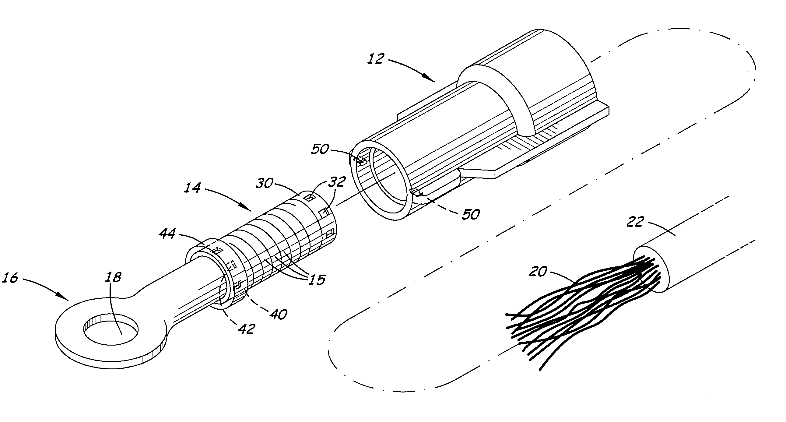
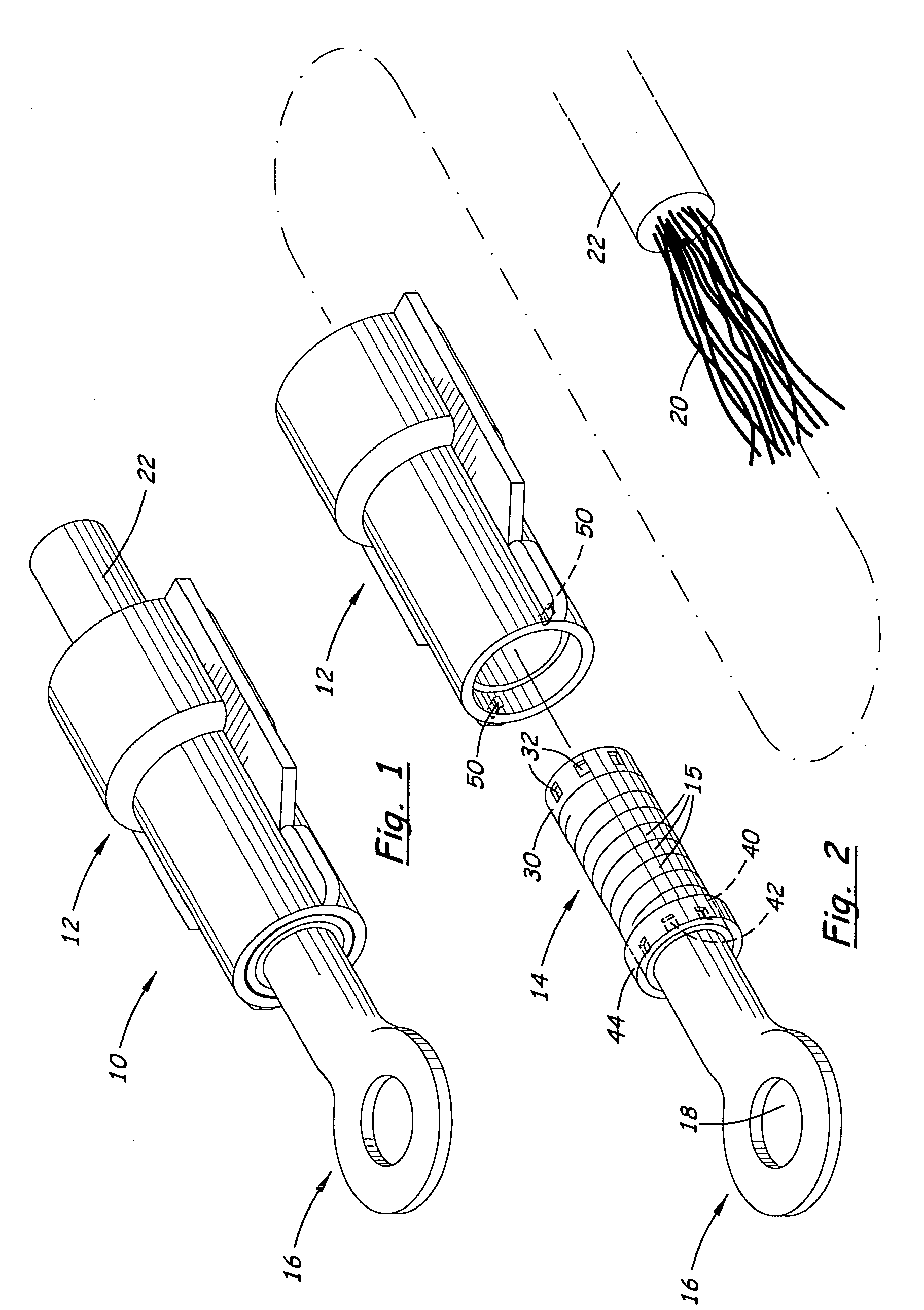
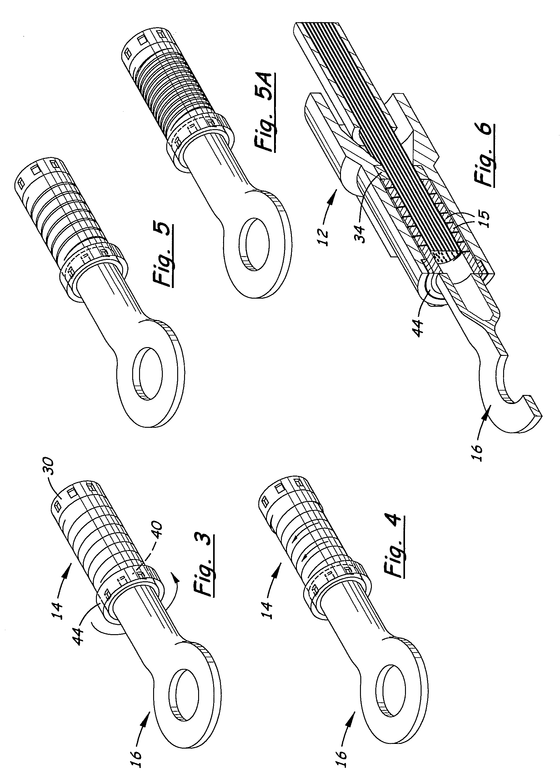
[0058]Referring to the Figures, there are shown several, but not the only, embodiments of the invented spiral electrical connectors. The invented connectors allow one or more stripped, electrically-conductive wires / cables / elements to be connected to other un-insulated, conductive wires / cables / elements. One may note that the term “conductive” is used in this Description and in the Claims for simplicity, and is understood to mean electrically-conductive. The invented connectors may be used with wire, cable, and other elongated conducting material, but the term “wire” is used herein for simplicity and includes single-strand, multiple-strand (including those that are braided, twisted, woven and / or otherwise grouped) wires and conducting material having at least a portion that is elongated for being inserted into the connector. The preferred embodiments are particularly beneficial in connecting multiple stripped, conductive strands (also called “filaments”) to each other or to another co...


PUM

PropertyMeasurementUnit
surface areaaaaaaaaaaa
diameteraaaaaaaaaa
diameteraaaaaaaaaa

Abstract

An electrical connector forms electrical contact by tightening of a movable, electrically-conductive spiral around un-insulated wire or wires. The spiral coils around the wire multiple times and tightens on the wire(s) when either one or the other end, or both ends, of the spiral is / are rotated relative to the other. One region of the spiral is preferably fixed to an insulating housing, while another region of the spiral may be rotated for the tightening on the wire and then preferably latched to the housing so that / the spiral remains in the tightened condition. A terminal end may extend from the spiral, or connectors without a terminal end may be used to electrically connect wires to each other that extend from and to other equipment not located on the connector itself. Multiple spirals may be provided in one connector, including spirals that tighten around separate wires at opposite ends of the connector. The connectors may be tightened quickly by hand, without tools, as one hand may grasp the housing or a housing portion, while the terminal end or another housing portion fixed to an end of the spiral (and consequently the spiral coils along with it) is twisted by the other hand.

Description

[0001]This application claims benefit of provisional application Ser. No. 61 / 030,470, filed Feb. 21, 2008; Ser. No. 61 / 054,770, filed May 20, 2008; Ser. No. 61 / 100,768, filed Sep. 29, 2008; and Ser. No. 61 / 106,473, filed Oct. 17, 2008, the disclosures of which are incorporated herein by this reference.BACKGROUND OF THE INVENTION[0002]1. Field of the Invention[0003]The invention relates generally to electrical connectors that connect multiple wires together, or that connect one or more wires to other electrically-conductive equipment. More specifically, the invention relates to a connector that comprises an electrically-conductive spiral for being tightened around conductive, stripped wire(s), wherein crimping is not required. In a loosened configuration, the conductive spiral is larger in diameter than the diameter of the stripped wire(s) being inserted into the spiral, but, after said insertion, the conductive spiral is manually tightened into a smaller-diameter configuration that ...

Claims


Application Information

Patent Timeline
Patent Type & Authority Patents(United States)
IPC IPC(8): H01R13/52
CPCH01R4/56H01R9/11H01R11/11H01R13/22H01R13/5205H01R4/12H01R11/12Y10T29/49204H01R4/4872H01R4/489H01R11/28
Inventor MELNI, MARK L.
Owner MELNI
Why Eureka
Try Eureka