
Method and apparatus of a twin-wire press

a twin-wire press and press body technology, applied in the field of methods and twin-wire presses, can solve the problems of high energy consumption for operation, high frictional force, and fiber web may be destroyed, and achieve the effect of improving the dewatering efficiency of fiber web and favorable dewatering

Inactive Publication Date: 2010-09-14
VALMET TECH INC
View PDF11 Cites 0 Cited by
  • Summary
  • Abstract
  • Description
  • Claims
  • Application Information

AI Technical Summary

Benefits of technology

"The present invention relates to a method and apparatus for dewatering a fiber suspension in a twin-wire press. The method involves transporting the fiber suspension through the press and compressing it between the wires using a separate pressing force to achieve a desired dryness of the fiber web. This method reduces friction and improves dewatering efficiency compared to conventional methods. The apparatus includes a pressing apparatus, such as a roll or a perforated dewatering element, which applies a separate pressing force against one of the wires to further dewater the fiber web. The technical effects of this invention include improved dewatering efficiency, reduced friction, and improved quality of the fiber web."

Problems solved by technology

Too large a loading of the dewatering tables directly results in high frictional forces and also very high energy consumption for the operation.
The step between the relatively slow dewatering in the dewatering tables and the very fast dewatering in the roll arrangement is considerable and may sometimes give rise to problems in the first roll nip in the roll arrangement.
In case the fiber web has far too low a pulp concentration when it leaves the dewatering tables, and is received and deformed with far too high a speed in the first roll nip in the roll arrangement, the fiber web may be destroyed.

Method used


Image

  • Method and apparatus of a twin-wire press
  • Method and apparatus of a twin-wire press
  • Method and apparatus of a twin-wire press

Examples


Embodiment Construction

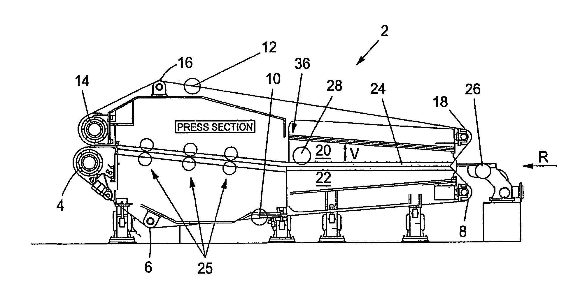
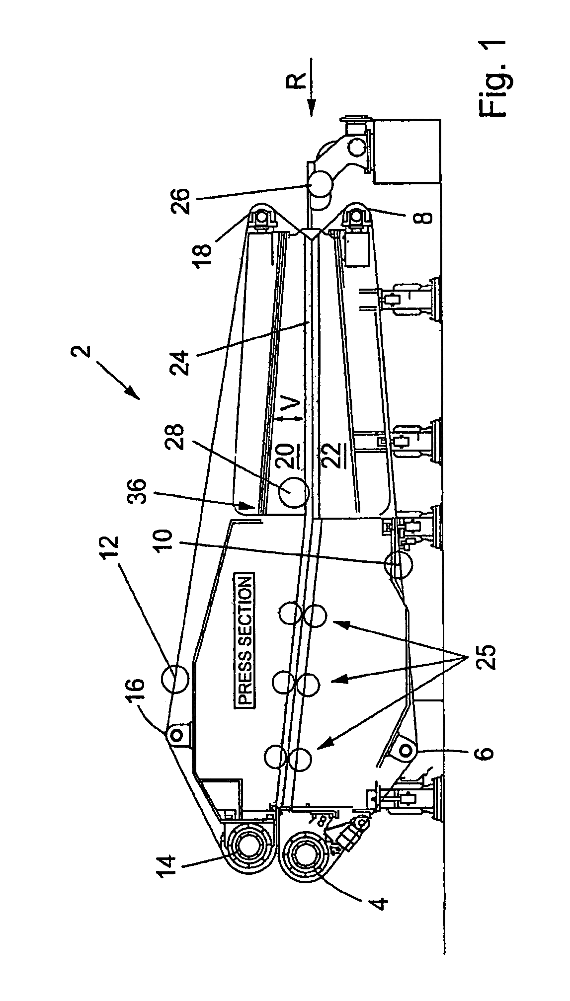
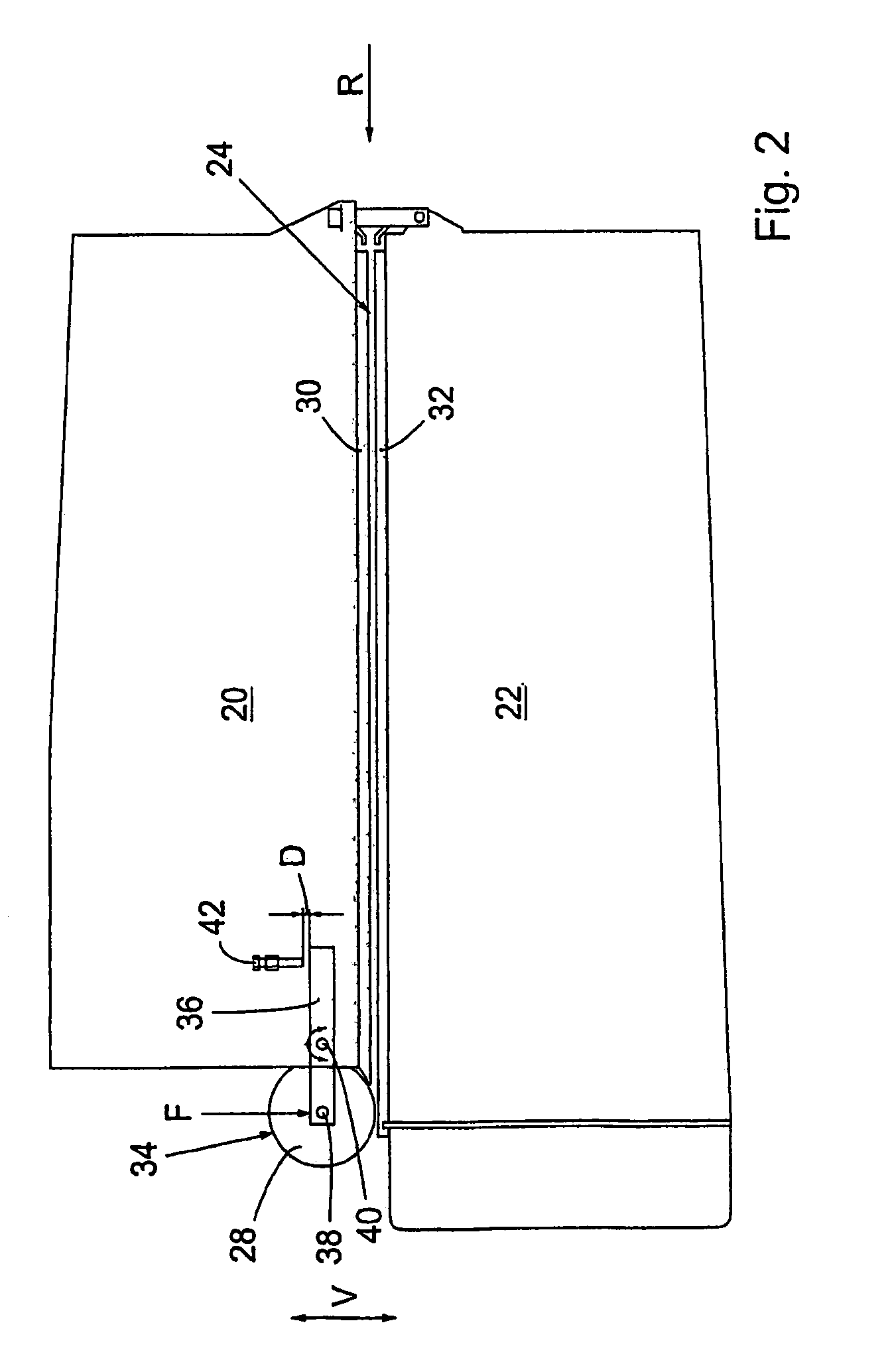
[0015]Referring to the Figures, in which like reference numerals refer to like elements thereof, FIG. 1 shows a twin-wire press 2 according to the present invention and which is suitable for carrying out the method according to the present invention. The twin-wire press 2 comprises three lower rolls, namely a drive roll 4, a control roll 6 and a tensioning roll 8. An endless lower wire 10 runs in a path around the lower rolls 4, 6 and 8. In a corresponding manner an upper endless wire 12 runs in a path around three upper rolls, namely a drive roll 14, a control roll 16 and a tensioning roll 18. An upper dewatering table 20, that supports the upper wire 12, and a lower dewatering table 22, that supports the lower wire 10, forms the dewatering space 24 between the wires 10, 12 in which the fiber suspension / web is dewatered under movement of the wires and compression between the dewatering tables (in a direction R, from the right to the left in the drawings), whereby the dewatered susp...


PUM

PropertyMeasurementUnit
pressing forceaaaaaaaaaa
concentrationaaaaaaaaaa
displacementaaaaaaaaaa

Abstract

Methods for dewatering a fiber suspension in a twin-wire press, having a lower wire and an upper wire, and a first and a second dewatering table, which supports the wires such that a dewatering space is defined by the wires, are disclosed. The wires transport the fiber suspension under compression of the wires by the dewatering tables, such that the fiber suspension is dewatered and forms a fiber web between the wires. A separate pressing force is applied against one of the wires, such that this wire presses the formed fiber web via the second wire against one of the dewatering tables and further dewaters the fiber web. The separate pressing force is adjusted such that a desired dryness of the fiber web leaving the dewatering tables is achieved. A twin-wire press is also disclosed.

Description

FIELD OF THE INVENTION[0001]The present invention relates to a method and a twin-wire press, for dewatering of a fiber suspension.BACKGROUND OF THE INVENTION[0002]Twin-wire presses for dewatering of a fiber suspension and forming of a continuous web thereof are previously known. Dewatering of the pulp is usually done from an inlet pulp concentration of from 3 to 8 percent by weight to an outlet pulp concentration of from 30 to 50 percent by weight. According to the state of the art, such twin-wire presses comprises lower rolls, an endless lower wire running in a path around the lower rolls, upper rolls, and an endless upper wire running in a path around the upper rolls. The two wires co-operate with each other along sections of said paths that run substantially in parallel with each other for dewatering of the fiber suspension between the wires during displacement thereof. An inlet box provides for supply of the fiber suspension to a wedge-shaped dewatering space between the wires. ...

Claims


Application Information

Patent Timeline
Patent Type & Authority Patents(United States)
IPC IPC(8): D21F1/80D21F3/06B30B9/24B30B5/06D21FD21F9/00
CPCB30B9/24D21F9/003D21F1/80B30B9/241D21F3/04
Inventor ODMARK, LEIF
Owner VALMET TECH INC
Learn More