
Method and Apparatus for Increasing Dewatering Efficiency

a technology of dewatering efficiency and method, applied in the direction of water/sewage treatment by oxidation, mixing, transportation and packaging, etc., can solve the problems of increased efficiency and undesirable increase in operational costs, and achieve the effect of improving dewatering efficiency, improving dewatering efficiency, and enhancing mixing

Active Publication Date: 2018-12-13
LEWIS F MICHAEL
View PDF0 Cites 6 Cited by
  • Summary
  • Abstract
  • Description
  • Claims
  • Application Information

AI Technical Summary

Benefits of technology

The present invention provides a method and apparatus for improving dewatering efficiency in wastewater treatment. It involves adding air and polymer to a sludge stream to aid in floc formation and water removal. The air and polymer are introduced into the sludge stream through a sparger, which infuses bubbles into the sludge stream at a specific location. This creates a turbulent and intense mixing of the components in the stream, improving mixing efficiency. Overall, this method and apparatus enhance the process of dewatering sludge in wastewater treatment.

Problems solved by technology

It has been a challenge for Waste Water Treatment Plants (WWTP) to treat and dispose of the increasing volumes of sludge, as the communities WWTPs serve are growing.
Unfortunately, increases in the efficiency of dewatering occur with increases in mixing energy or increases in polymer dosing, which are accompanied by undesirable increases in operational costs.

Method used


Image

  • Method and Apparatus for Increasing Dewatering Efficiency
  • Method and Apparatus for Increasing Dewatering Efficiency
  • Method and Apparatus for Increasing Dewatering Efficiency

Examples


Embodiment Construction

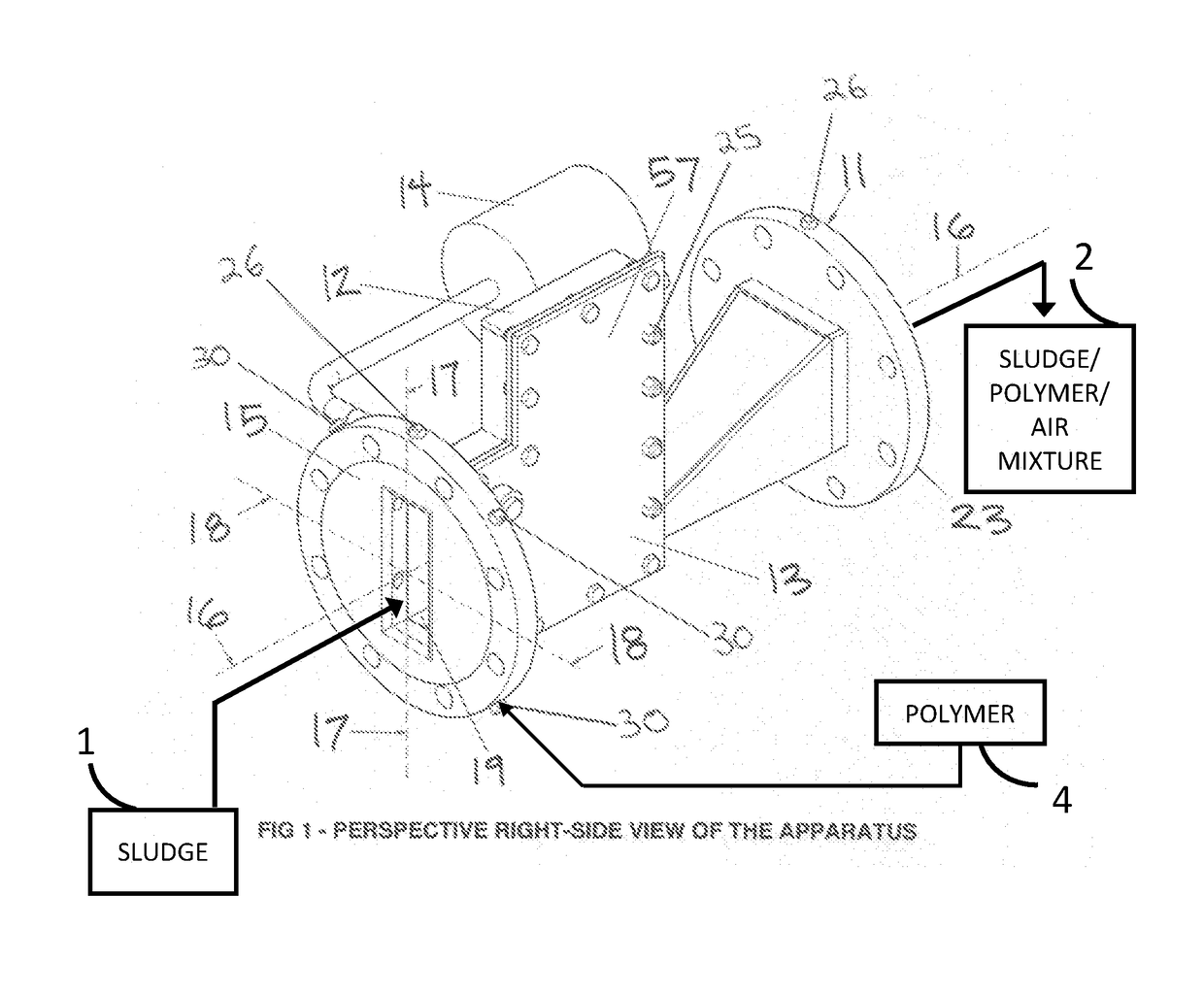
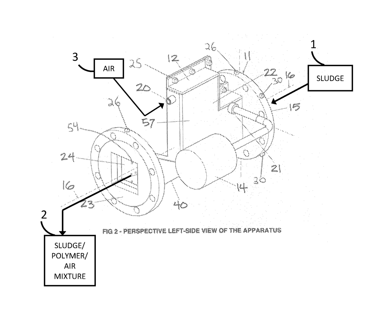
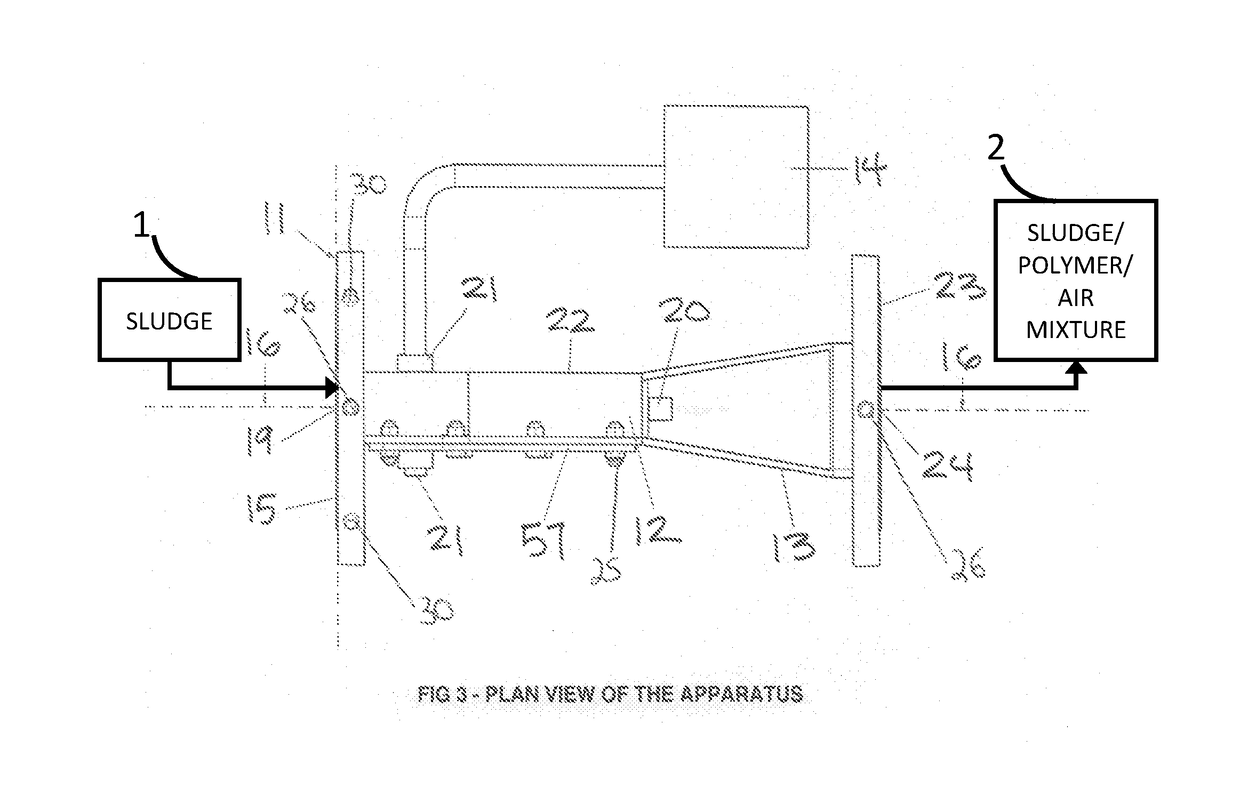
[0101]A method and apparatus to increase the efficiency of downstream dewatering in wastewater treatment through a cost-effective increase in the mixing efficiency of a sludge-polymer-air aqueous stream according to a preferred embodiment of the present invention will now be described with reference to FIGS. 1-9.

[0102]Referring now to FIG. 1 of the drawings, the apparatus 11 will receive the influent sludge 1 stream through its sludge flow inlet 19 at the front of the apparatus 15, and may pass through the apparatus 11 to the back of the apparatus 23, along the longitudinal axis 16, so that the sludge flow may be mixed with air from an air source 3 and polymer from a polymer source 4 in the zone of intense mixing 50.

[0103]Referring now to FIG. 2 of the drawings, the apparatus discharges its sludge-polymer-air stream 2 through its sludge flow outlet 24 at the back of the apparatus 23, after passing through the apparatus 11 along the longitudinal axis 16, where the sludge 1 will have ...


PUM

PropertyMeasurementUnit
areaaaaaaaaaaa
widthaaaaaaaaaa
pressureaaaaaaaaaa

Abstract

A method and apparatus for increasing dewatering efficiency of a solids-laden liquid stream in a wastewater treatment facility, whereby a liquids-solids stream is pumped into a mixing apparatus in a closed-channel liquid flow conduit configuration, where the liquids-solids stream is intensely mixed with air and polymer in a mixing zone created by an adjustable flow restriction device, performing similar to a venturi to increase the velocity, agitation, and turbulence of the liquids-solids stream internal to the mixer, where the introduction of air and polymer to the stream is introduced independent of mixing energy. Compared with current methods and apparatuses to mix polymer with solids-laden wastewater, the present method and apparatus requires less energy, where it enables the addition of air independent of mixing energy, and it creates a zone of mixing with greater mixing efficiency via increased turbulence.

Description

CROSS-REFERENCE TO RELATED APPLICATIONS[0001]This application claims the benefit of U.S. Provisional Patent Application No. 62 / 444,012, filed Jan. 9, 2017 by the present inventorFEDERALLY SPONSORED RESEARCH[0002]None.SEQUENCE LISTING[0003]None.BACKGROUNDPrior Art[0004]The following is a tabulation of some prior art that presently appears relevant:U.S. Patents[0005]Patent NumberPriority DateInventorU.S. Pat. No. 7,014,775March 2002Sharpe et al.U.S. Pat. No. 5,820,256May 1996MorrisonU.S. Pat. No. 5,514,267May 1996Machiya et al.U.S. Pat. No. 4,337,152September 1978LynchU.S. Pat. No. 4,303,470June 1979Meredith et al.U.S. Pat. No. 3,661,364February 1968LageU.S. Pat. No. 3,666,663 ANovember 1969WalkerU.S. Pat. No. 3,334,868November 1962LageU.S. Patent Application Publications[0006]Publication NumberPubl. DateAssigneeUS 2013 / 0220937 A1August 2013OregeNonpatent Literature Documents[0007]Takagi, Shu, and Matsumoto, Y., Annual Review of Fluid Mechanics, Vol. 43, “Surfactant Effect on Multisca...

Claims


Application Information

Patent Timeline
Patent Type & Authority Applications(United States)
IPC IPC(8): C02F11/14B01F3/04B01F5/00B01F5/04
CPCC02F11/14B01F3/0412B01F5/0065B01F5/0405B01F2005/0017B01F2005/0051B01F2215/0052C02F1/74C02F11/147B01F23/2323B01F25/31241B01F23/2311B01F25/103B01F25/311B01F2025/913B01F2025/919125B01F2101/305
Inventor LEWIS, F. MICHAEL
Owner LEWIS F MICHAEL
Learn More