
System and method for lead implantation in a pericardial space

Inactive Publication Date: 2010-09-14
PACESETTER INC
View PDF13 Cites 89 Cited by
  • Summary
  • Abstract
  • Description
  • Claims
  • Application Information

AI Technical Summary

Benefits of technology

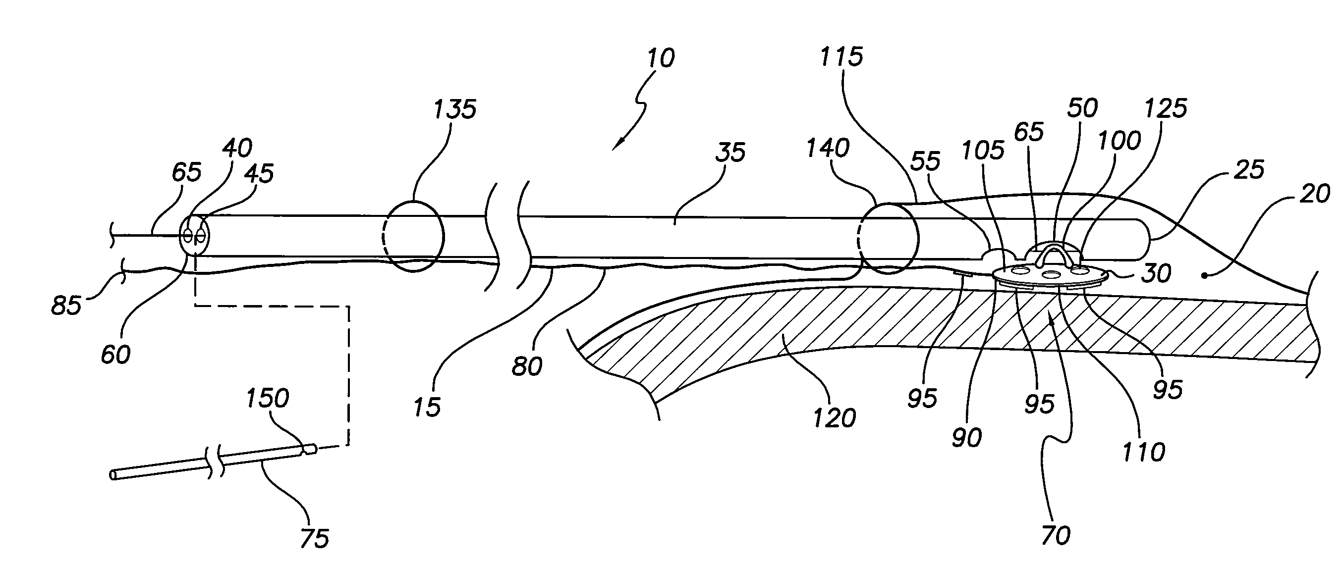
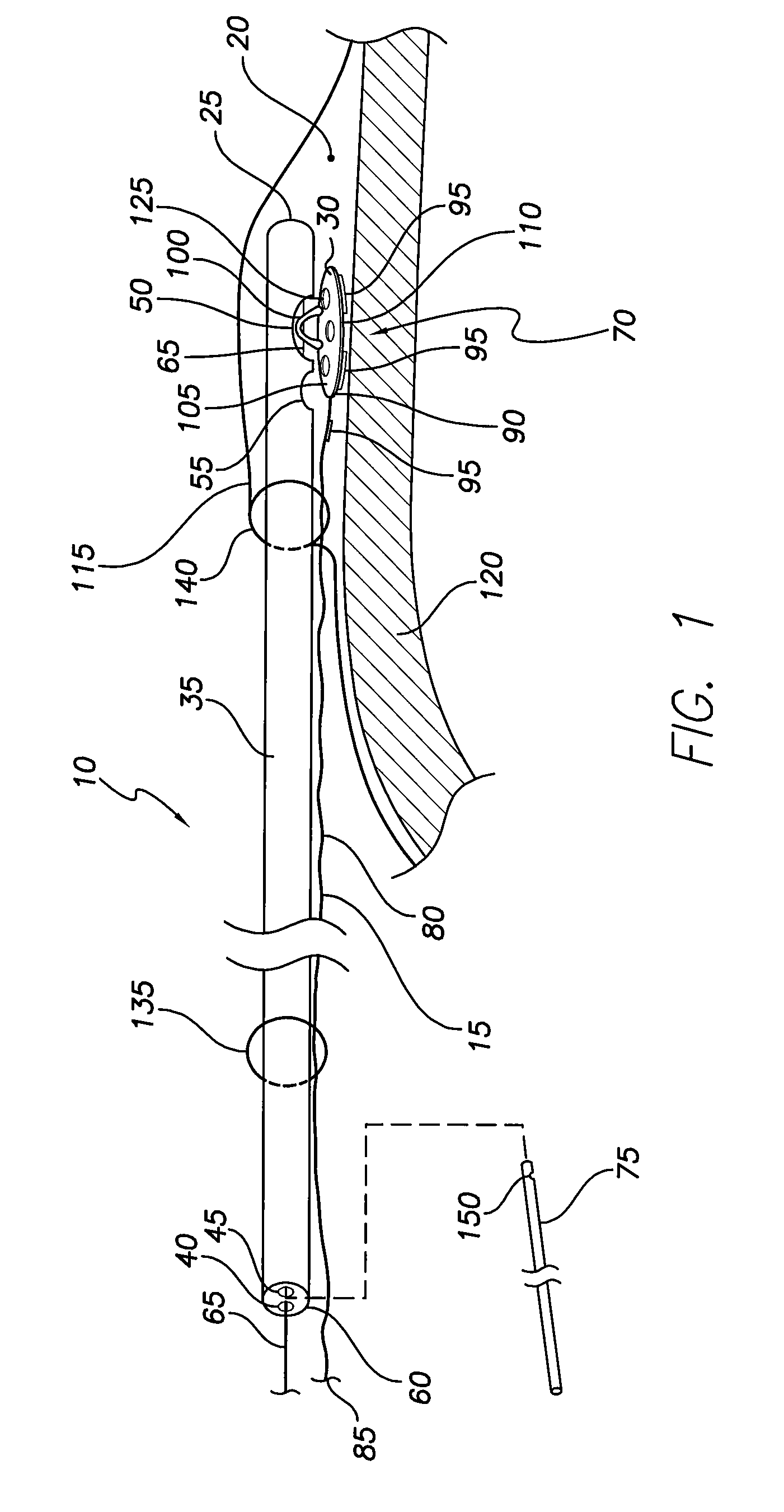
[0005]A system for pericardial lead implantation is disclosed herein. In one embodiment the system includes an implantation tool and a stimulation lead. The implantation tool includes a tubular body, a first lumen, a second lumen, a stylet or guidewire, a first port, and a second port. The first and second lumens longitudinally extend through tubular body. The first port is in communication with the first lumen, and the second port is in communication with the second lumen. The stylet or guidewire is longitudinally displaceable in

Problems solved by technology

Despite the great promise shown by the minimally invasive pericardial approach, a current challenge continues to be an inability to reliably achieve a mechanically and electrically stable fixation of a stimulation lead at a preferred implantation site within the pericardial space.

Method used


Image

  • System and method for lead implantation in a pericardial space
  • System and method for lead implantation in a pericardial space
  • System and method for lead implantation in a pericardial space

Examples


Embodiment Construction

[0011]An implant tool 10 and method for implanting a stimulation lead 15 (e.g., pacing and / or defibrillation lead) are disclosed herein. The implant tool 10 and method are advantageous in that they allow a lead 15 to be slid into position within the pericardial space 20 and then dropped to achieve a mechanically and electrically stable atraumatic fixation to the implant location.

[0012]For a discussion of the device 10, reference is made to FIG. 1, which is a diagrammatic depiction of a distal end 25 of the implant tool 10 located within the pericardial space 20 and coupled to a distal end 30 of the lead 15. As shown in FIG. 1, the tool 10 includes a tubular body 35, a first lumen 40, a second lumen 45, a first port 50 and a second port 55. The tubular body 35 includes distal and proximal ends 25, 60. The first lumen 40 extends the length of the tubular body 35 and daylights or opens at the distal and proximal ends 25, 60. The first port 50 connects to the first lumen 40 and opens th...


PUM


Abstract

A system for pericardial lead implantation is disclosed herein. The system includes an implantation tool and a stimulation lead. The implantation tool includes a tubular body, a first lumen, a second lumen, a stylet or guidewire, a first port, and a second port. The first and second lumens longitudinally extend through tubular body. The first port is in communication with the first lumen, and the second port is in communication with the second lumen. The stylet or guidewire is longitudinally displaceable in the first lumen and across the first port. A tissue adhesive is selectively administrable through the second port via the second lumen. The stimulation lead includes a distal end and an engagement feature. Placing the engagement feature in the first port and causing the stylet or guidewire to displace in a first direction across the first port causes the lead to attach to the implantation tool. Displacing the stylet or guidewire in a second direction opposite the first direction allows the lead to detach from the implantation tool.

Description

FIELD OF THE INVENTION[0001]The present invention relates to medical devices and methods. More specifically, the present invention relates to devices and methods of implanting pacing and defibrillation leads.BACKGROUND OF THE INVENTION[0002]Factors (e.g., coronary sinus obstructions, absence of a suitable cardiac vein, high thresholds, or pheric nerve stimulation) warrant the need for an alternative to a transvenous approach to the implantation of left ventricle (“LV”) leads in congestive heart failure (“CHF”) patients in need of cardiac rhythm treatment (“CRT”). Historically, the alternative to a transvenous approach has entailed placement of an epicardial lead, which required invasive surgery and an associated hospital stay.[0003]A minimally invasive pericardial approach to implanting a stimulating lead (e.g., a LV lead) has shown great promise as an alternative to the aforementioned transvenous and invasive surgery methods. In the pericardial approach, an introducer sheath is use...

Claims


Application Information

Patent Timeline
IPC IPC(8): A61N1/05
CPCA61N1/0587
Inventor BORNZIN, GENE A.CHITRE, YOUGANDHPOORE, JOHN W.
Owner PACESETTER INC
Learn More