Rotary tissue removing instrument

a tissue removing and rotary technology, applied in the field of rotary tissue removing instruments, can solve the problems of granulation tissue removal, time-consuming and tedious process, and difficulty in cutting or scraping granulation tissue and removal,

Inactive Publication Date: 2010-09-21
HARREL STEPHEN K
View PDF8 Cites 47 Cited by
  • Summary
  • Abstract
  • Description
  • Claims
  • Application Information

AI Technical Summary

Problems solved by technology

The removal of granulation tissue by a curette is a time consuming and tedious process, often taking 5-8 minutes per tooth.
In this instance it becomes extremely difficult to cut or scrape the granulation tissue and remove it.

Method used


Image

  • Rotary tissue removing instrument
  • Rotary tissue removing instrument
  • Rotary tissue removing instrument

Examples


Embodiment Construction

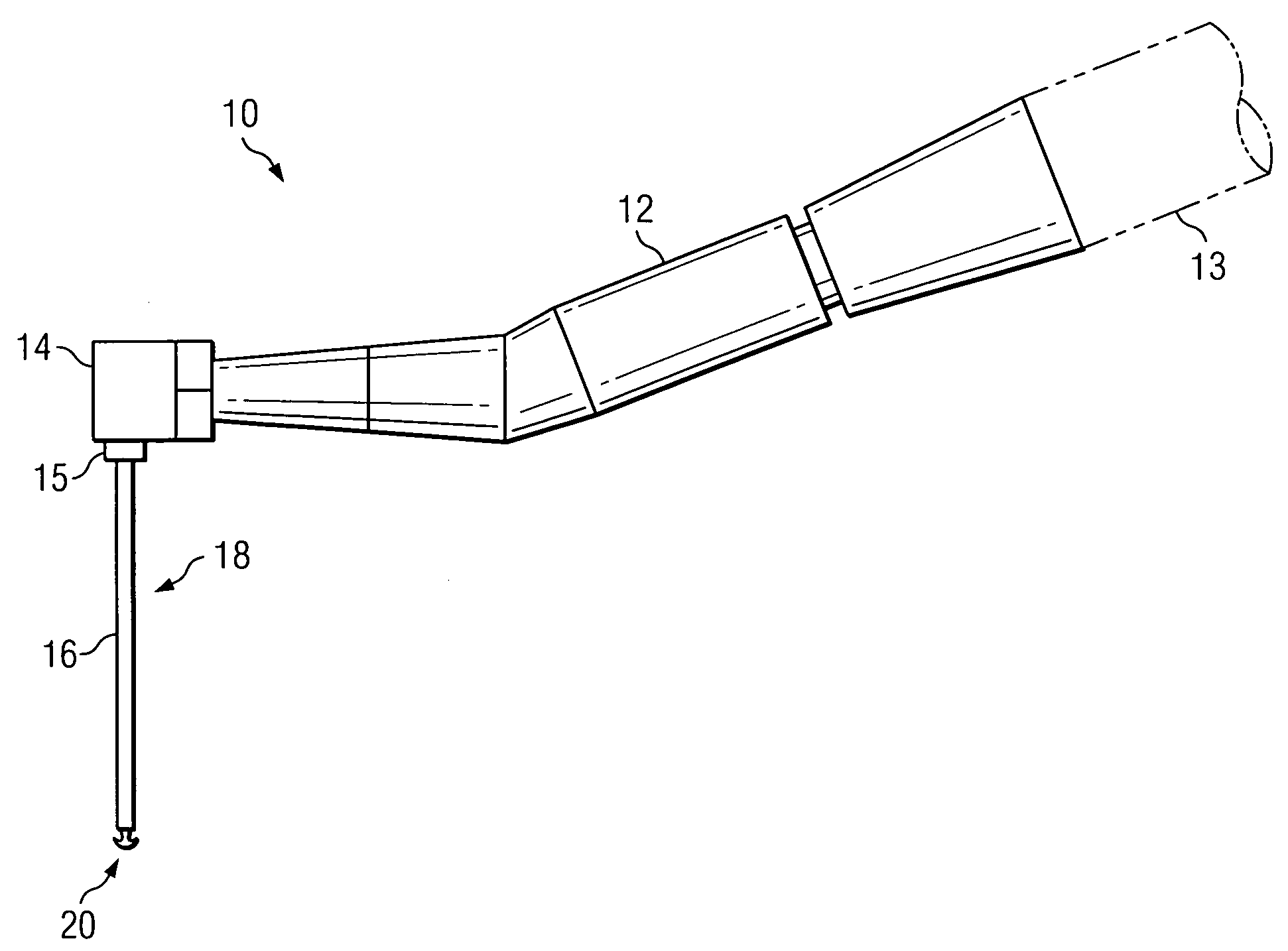
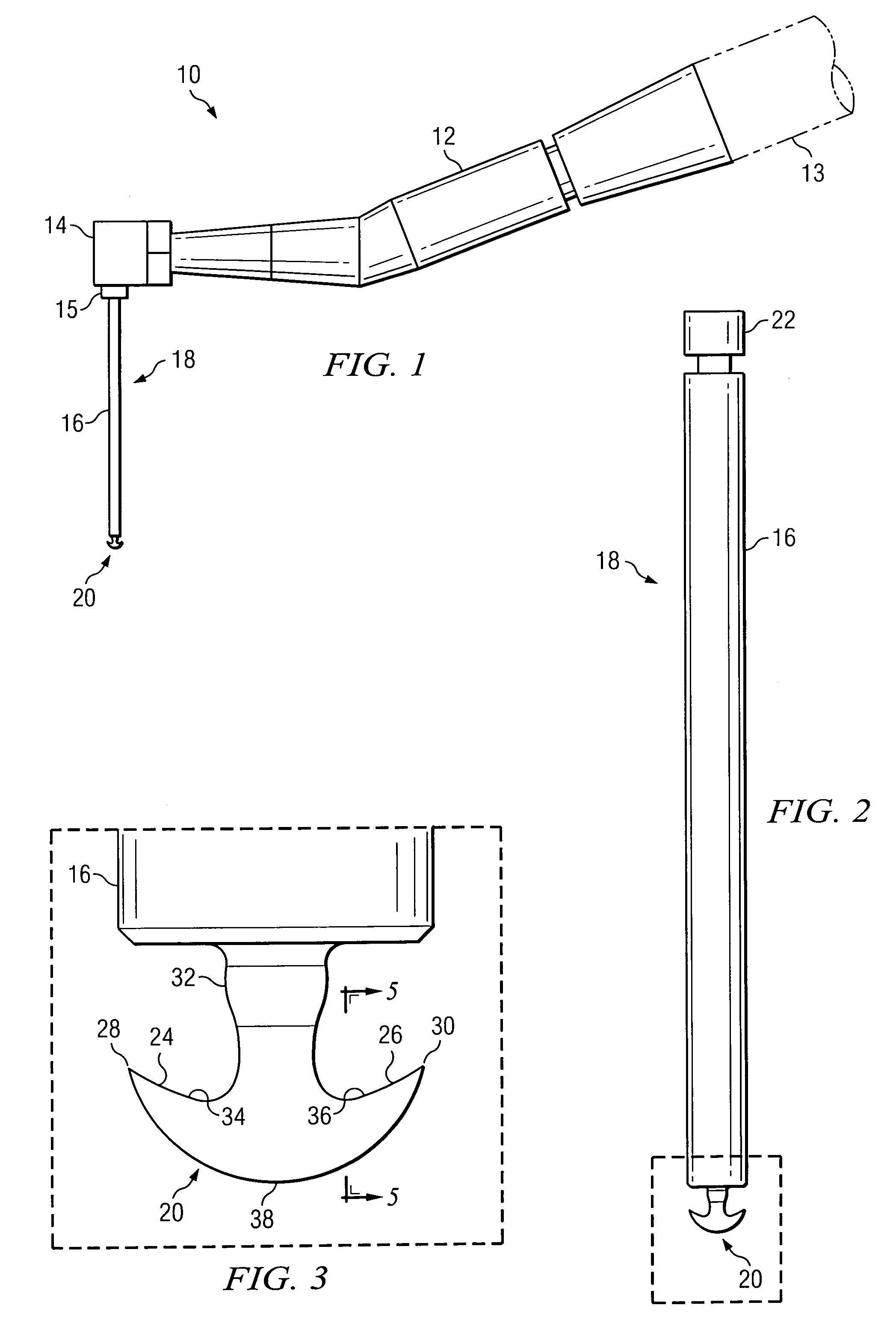
[0027]With reference to FIG. 1, there is shown a power-driven tool with which the tissue removing instrument of the invention is advantageously practiced. The power driven tool 10 is shown as a hand-held device, which may be available in many other forms. The power-driven tool 10 is of conventional construction, including a body 12 which is removably attached to an air-driven rotary motor assembly 13. A head 14 of the tool 10 houses a friction-type chuck 15 for holding the shank 16 of the tissue removing instrument 18 therein. While not shown, the tool 10 includes an internal shaft so that the air-driven motor can rotate the shaft or shank of any instrument or bit inserted into the chuck 15. The instrument 18 includes a tissue engaging member 20 attached to the end of the shank 16. The instrument 18 can be removed from the chuck 15 by forcefully pulling it therefrom.

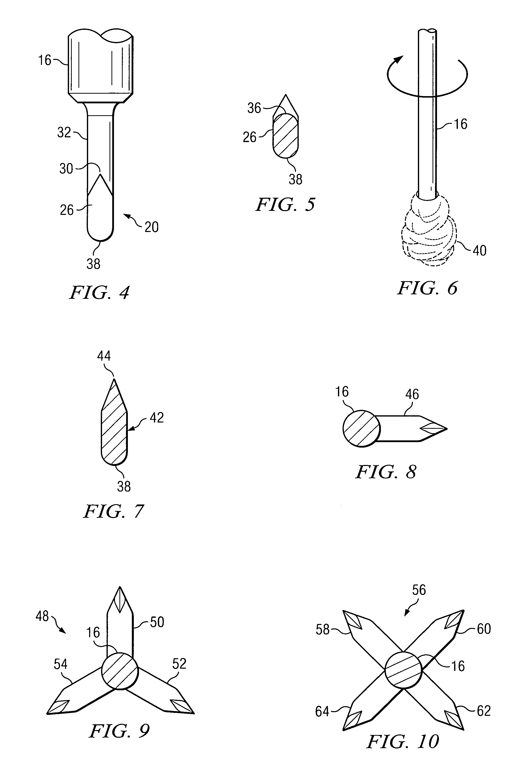
[0028]The tissue removing instrument 18 according to one embodiment of the invention is illustrated in FIG. 2, and in ...


PUM


Abstract

A rotatable tissue removing instrument having a tissue engaging member. The tissue engaging member includes one or more prongs or barbs, or both, which grab the strands of granulation tissue and cause the tissue to be wrapped around the tissue engaging member. The granulation tissue continues to be wrapped around the tissue engaging member until pulled free from both the tooth and the bone.

Description

BACKGROUND OF THE INVENTION[0001]Medical and dental practice often requires the surgical removal of both hard and soft tissue in the treatment of a patient. The removal of damaged tissue or scar tissue is often necessary in order to prevent deterioration of associated or neighboring healthy tissue. For example, in the treatment of periodontal diseases, such as periodontitis, the removal of granulation tissue is necessary in order to arrest further deterioration of both the hard bony tissue and soft gingival tissue. Granulation tissue is the diseased gingival tissue that is attached to the bone around the tooth. The granulation tissue has a stringy consistency and must be removed before the healthy gingival tissue and the bone can regenerate and reattach to the tooth.[0002]The current practice in removing the granulation or scar tissue adjacent a tooth is with the use of a curette. By continually scraping the granulation tissue with the curette, the sinewy tissue fibers are disconnec...

Claims


Application Information

Patent Timeline
Patent Type & Authority Patents(United States)
IPC IPC(8): A61C5/00
CPCA61C3/02A61C5/02A61C5/40
Inventor HARREL, STEPHEN K.
Owner HARREL STEPHEN K
Why Eureka
Try Eureka