

Method and system for shot tracking
a technology of shot tracking and circuit, applied in the field of shot tracking, can solve the problems of increasing sophistication, increasing power depletion, and no longer useful devices, and achieve the effect of preserving power and imparting intelligence to the circui
- Summary
- Abstract
- Description
- Claims
- Application Information
AI Technical Summary
Benefits of technology
Problems solved by technology
Method used
Image

Examples
Embodiment Construction
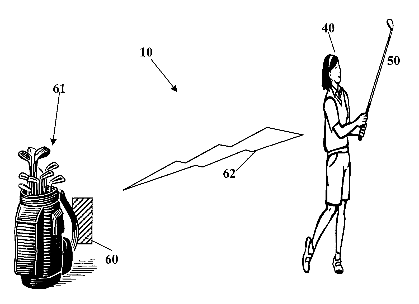
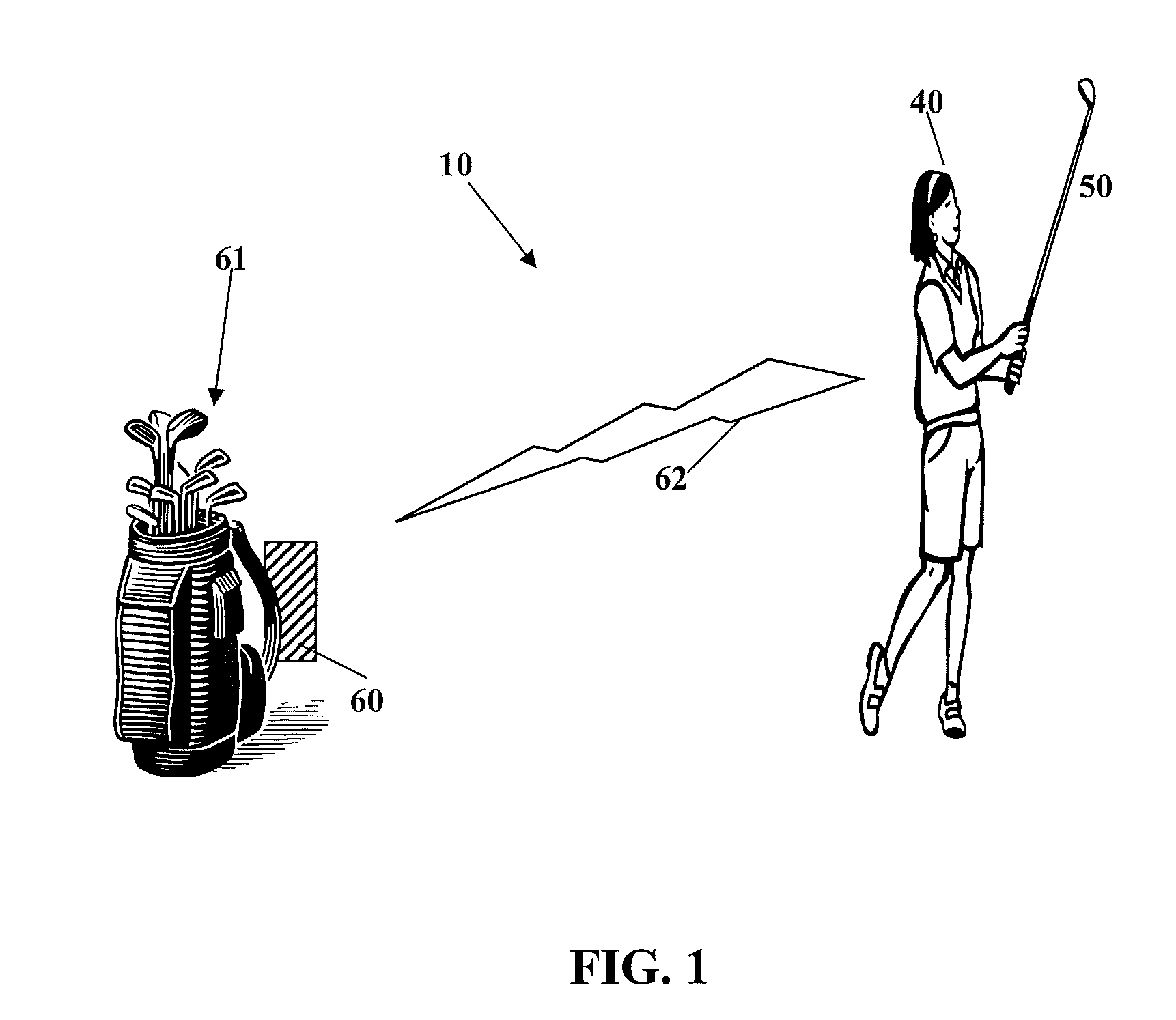
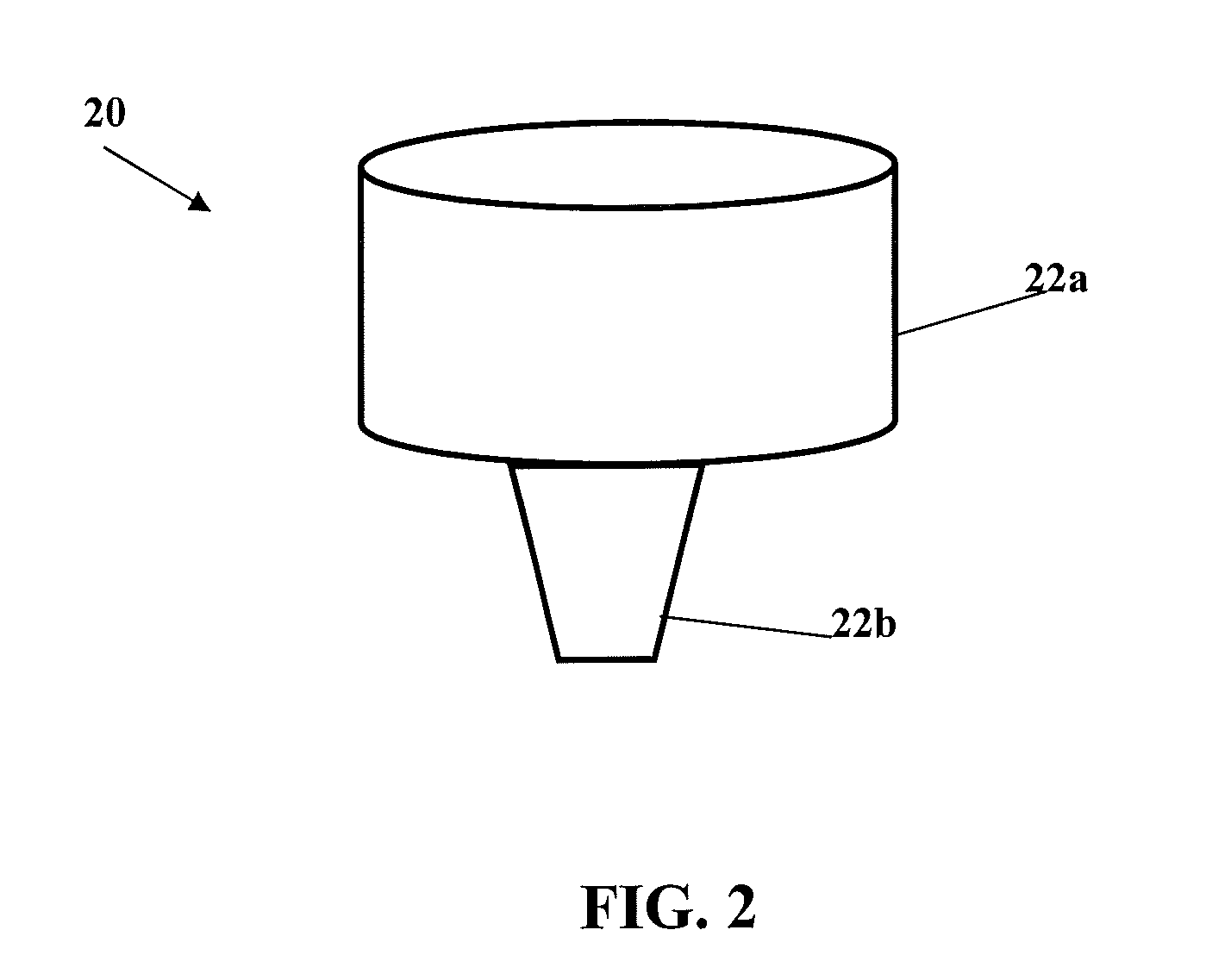
[0021]A system for shot tracking is illustrated in FIG. 1. A golfer 40 strikes a golf ball with a golf club 50. The golf club 50 includes a device 20 preferably positioned within a grip. The device 20 includes a circuit 25 for transmitting a RFID signal while conserving the battery power of the device 20. The RFID signal 62 is preferably transmitted to a receiver 60 attached to a golf bag 61. As discussed in greater detail below, the RFID signal preferably comprises the golf club 50 used by the golfer and golf swing information.
[0022]The receiver 60 is preferably a GPS device such as disclosed in Balardeta et al., U.S. Patent Publication Number 20090075761 for a Golf GPS Device And System, which is hereby incorporated by reference in its entirety. Alternatively, the receiver is a personal digital assistant (PDA), “smart phone”, mobile phone, or other similar device. However, those skilled in the pertinent art will recognize that the receiver may be any type of receiver capable of re...
PUM
 Abstract
Description
Claims
Application Information