Method of manufacturing an ophthalmic lens for providing an optical display

a manufacturing method and technology for ophthalmic lenses, applied in the field of manufacturing ophthalmic lenses for optical displays, can solve the problems of inability to achieve a compromise between display function and vision correction function, the lens thickness becomes unacceptable, and the display cannot be reasonably adapted to a vision-correcting lens

Active Publication Date: 2010-09-21
ESSILOR INT CIE GEN DOPTIQUE
View PDF8 Cites 16 Cited by
  • Summary
  • Abstract
  • Description
  • Claims
  • Application Information

AI Technical Summary

Benefits of technology

[0011]The invention solves this problem by providing a method of manufacturing an ophthalmic display that can also correct the vision of a user, while being mass-produced in reliable manner, with this being achieved by decoupling the display and the vision-correction functions.

Problems solved by technology

This goes against obtaining a lens fitted in this way that also serves to correct vision.
Given the curved correcting surfaces at the front and the rear of an ophthalmic lens and given the curvatures that depend on the vision correction to be provided, the overall thickness of the lens becomes unacceptable.
Although those types of display enable a lens to be obtained of smaller thickness, they raise a problem of achieving a compromise between the display function and the vision correction function.
In practice, such displays thus cannot be reasonably adapted to a vision-correcting lens.

Method used


Image

  • Method of manufacturing an ophthalmic lens for providing an optical display
  • Method of manufacturing an ophthalmic lens for providing an optical display
  • Method of manufacturing an ophthalmic lens for providing an optical display

Examples


Embodiment Construction

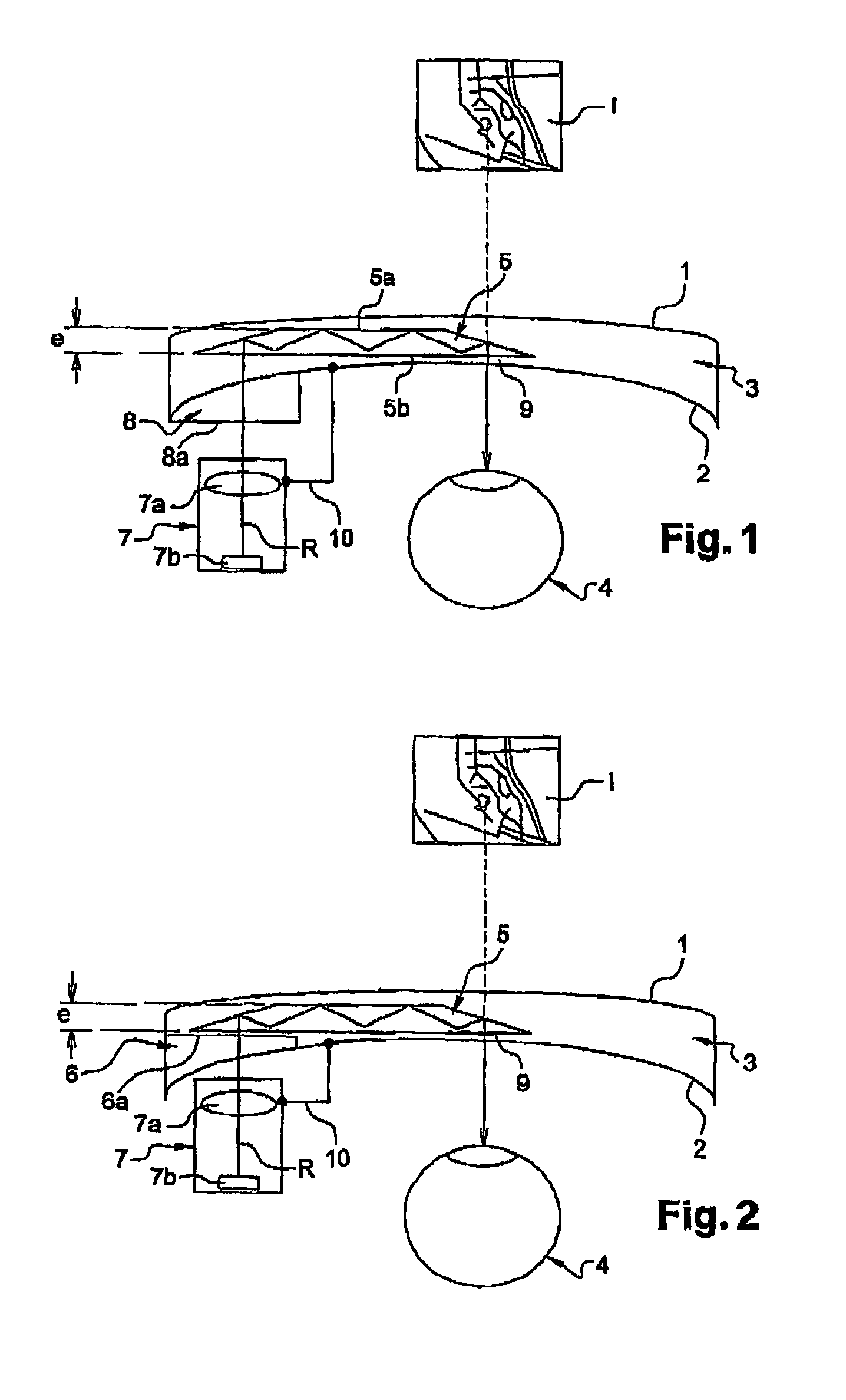
[0037]With reference to FIG. 1, an electronic signal carrying information is delivered to a miniature screen 7b by a cable (not shown). From this signal, the miniature screen 7b, which is back-lighted, generates an image made up of pixels corresponding to the information. The screen 7b is associated with an optical device 7a. The light beam generator system 7 formed by the screen and the optical device is positioned relative to a lens 3 by means of a mechanical interface 10. A protective shell generally protects all or part of the assembly.

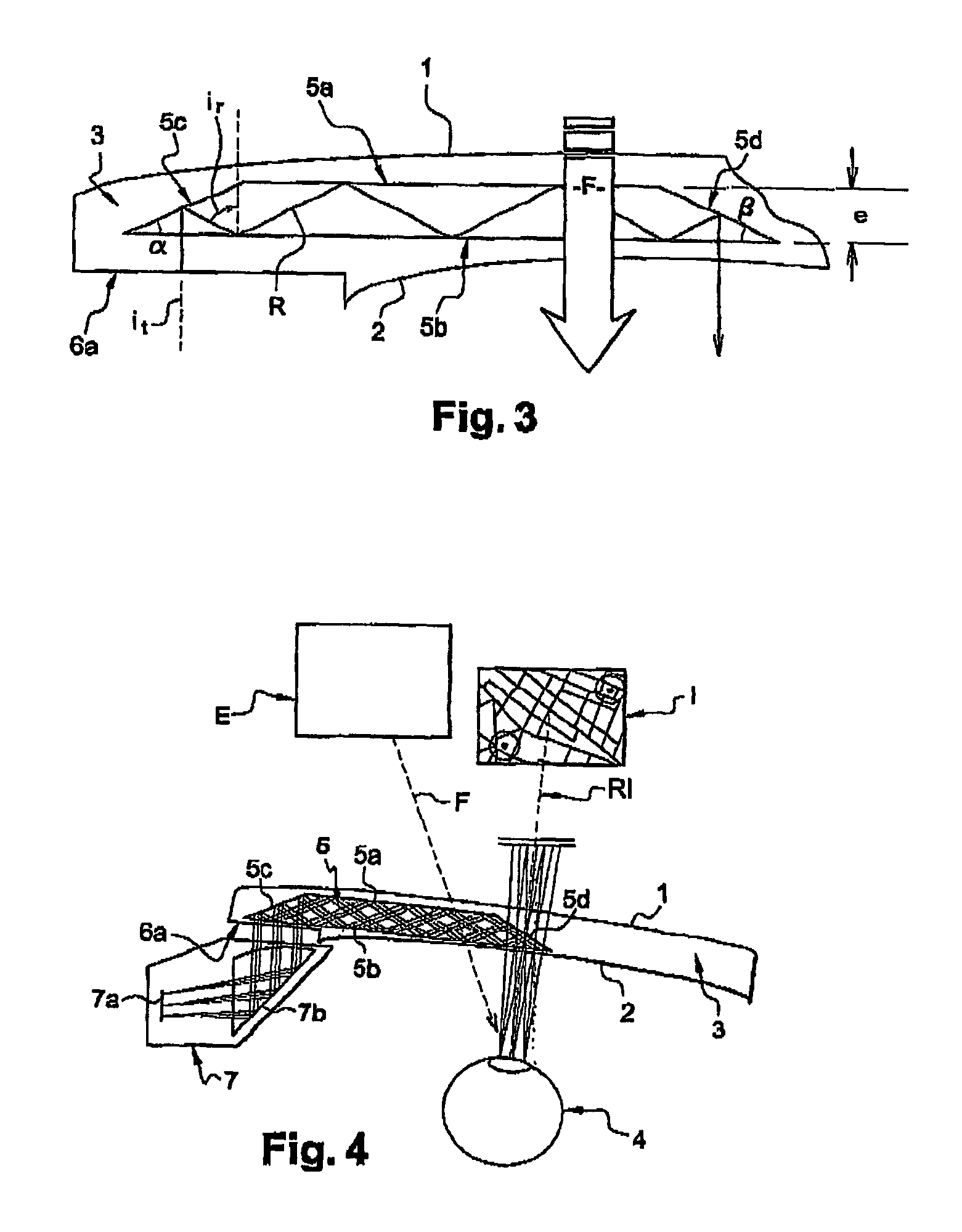
[0038]The light beam as represented by the path of the principal ray R is thus directed towards the lens 3 and penetrates therein via an entry surface 8a associated with the lens 3. This entry surface 8a and the path of the principal ray R are substantially perpendicular.

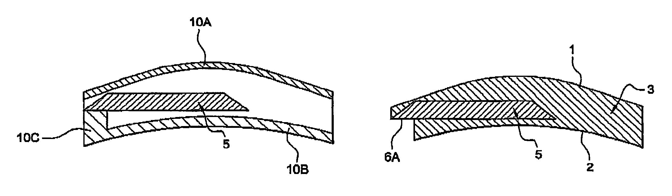
[0039]The entry surface 8a is formed by an insertion piece 8 fitted on the rear face 2 of the lens 3 and secured for example by adhesive. This surface 8a may be made, for example,...


PUM


Abstract

The invention relates to a method of manufacturing a vision correction lens that has a front face and a rear face, and into which light beams emitted by an optical element of a light beam generator system are introduced via an entry surface and directed towards the eye of the wearer to enable information content to be viewed, said light beams being reflected a plurality of times between two “reflection” faces between being introduced into the lens and exiting therefrom, said two reflection faces being faces of a transparent optical insert constituted by a light guide. According to the invention, said insert is completely contained within the lens.

Description

RELATED APPLICATIONS[0001]The present application is a national phase application of PCT / FR2005 / 050574, which in turn claims the benefit of priority from French Patent Applications No. 04 07902, filed on Jul. 16, 2004, the entirety of which are incorporated herein by reference.FIELD OF THE INVENTION[0002]The present invention relates to a method of manufacturing an ophthalmic lens for making an optical display by means of an optical imager designed to allow information of the image or multimedia type to be projected. The term “lens” is used herein to designate an optical system suitable in particular for being positioned in a frame for spectacles or eyeglasses.BACKGROUND OF THE INVENTION:[0003]U.S. Pat. No. 5,886,822 discloses making an ophthalmic lens that presents a projection insert. Such a projection insert is constituted by an optical imager for shaping the light beams coming from an electronic and optical system for generating light beams based on an electronic signal, the sys...

Claims


Application Information

Patent Timeline
Patent Type & Authority Patents(United States)
IPC IPC(8): G02B27/14G02B6/00G02B27/01G02C5/00
CPCG02B6/10G02C7/086G02B27/0172B29D11/00G02B3/00G02B27/01G02C7/02
Inventor MOLITON, RENAUDCADO, HERVEMARTIN, GERARD
Owner ESSILOR INT CIE GEN DOPTIQUE
Why Eureka
Try Eureka