Vehicle having non-circular wheels propelled by a moving weight

a non-circular, weight-bearing technology, applied in the field of vehicles, can solve the problems of excessive complexity, excessive cost of achieving any valuable function, and complicated apparatus, and achieve the effect of facilitating movement over uneven terrain and minimizing any problems with wheel dragging

Inactive Publication Date: 2010-09-28
WINCKLER JASON M +1
View PDF20 Cites 56 Cited by
  • Summary
  • Abstract
  • Description
  • Claims
  • Application Information

AI Technical Summary

Benefits of technology

[0011]In a further preferred embodiment, each non-circular wheel on the vehicle defines the same number of segments, and each wheel also defines the same angle between segments of each wheel. Because the angle between the segments is the same, the vehicle may readily travel in a forward or rearward direction of travel based upon whether the offset arm is moving in a clockwise or a counter clockwise direction.
[0012]Because the non-circular wheels are firmly secured through mechanical linkage and / or the axles, in certain embodiments steering the vehicle requires a non-traditional steering mechanism. In other embodiments, conventional steering may be utilized, especially where the vehicle is moving slowly and one of the non-circular wheels tends to lift as the wheels turn, minimizing any problems with a wheel dragging while turning with a conventional steering mechanism. In a certain embodiment, the vehicle may be steered by articulation of the frame about a center or pivot point. In another embodiment, steering may be achieved by having wheels on one side be or become greater in size. Additionally, steering may be achieved by a rotating plate that descends at predetermined intervals to the support surface to lift and rotate the frame to a desired orientation. Additionally, if the wheels were rotated about a vertical axis (like a conventional steering mechanism), and aligned so that they all tended to move around a circle, the car would rotate or turn about a vertical axis as the weight (force) was moved, thus changing the direction of the car. In such circumstances, whether the sequential alignment of the non-circular wheels is oriented to be clockwise or counter clockwise would determine whether the vehicle would turn in the same direction as the rotation of the force (or weight) or counter to that direction.
[0013]In yet another embodiment, the non-circular wheels may be in the form of spokes without a rim or may be in the form of star-shaped rods having no material between non-central end-points of the rods, wherein the end-points of the rods define vertices on a perimeter of a polygon. This would further facilitate movement over uneven terrain. The end-points may also be covered with support pads or they may form rounded tips, and the tips may also be of resilient material to further cushion movement of the vehicle.
[0019]It is a more specific purpose to provide a vehicle having non-circular wheels propelled by a moving weight that readily moves over uneven terrain and that also minimizes manufacturing and operating costs of the vehicle.

Problems solved by technology

Delroy, however, is extraordinarily complex, and therefore too costly to achieve any valuable function.
All of these and other known efforts to produce a vehicle that propels itself without a rotational force applied directly to circular wheels, or directly to drive wheels such as in tracked vehicles, involve extraordinarily complex apparatus that would be very costly to manufacture.
Perhaps more importantly, known efforts have not been successful at engaging rough terrain and have not produced an efficient use of the rotational force, compared to traditional, circular wheeled vehicles.

Method used


Image

  • Vehicle having non-circular wheels propelled by a moving weight
  • Vehicle having non-circular wheels propelled by a moving weight
  • Vehicle having non-circular wheels propelled by a moving weight

Examples


Embodiment Construction

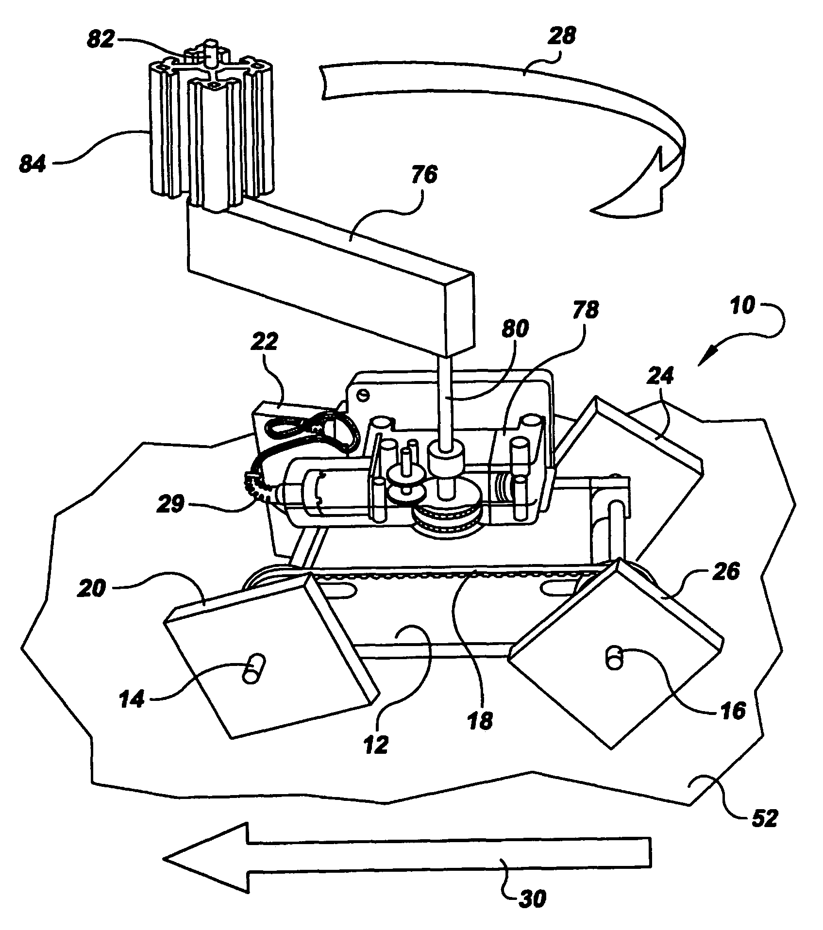
[0029]Referring to the drawings in detail, a vehicle having non-circular wheels is shown in FIG. 1, and is generally designated by the reference numeral 10. The vehicle 10 includes a frame 12 having a first axle 14 and a second axle 16, and a linkage means secured between the first and second axles 14, 16 for rotating the first axle 14 upon rotation of the second axle 16 and for rotation of the second axle 16 upon rotation of the first axle 14, such as a gear belt, chain, or any known mechanical connection 18 extending between the axles 14, 16. Additionally, the linkage means may include direct mechanical, hydraulic, electric, or any known linkage means capable of rotating all non-circular wheels upon the rotation of one of the non-circular wheels, wherein the linkage means 18 replaces the first and second axles 14, 16.

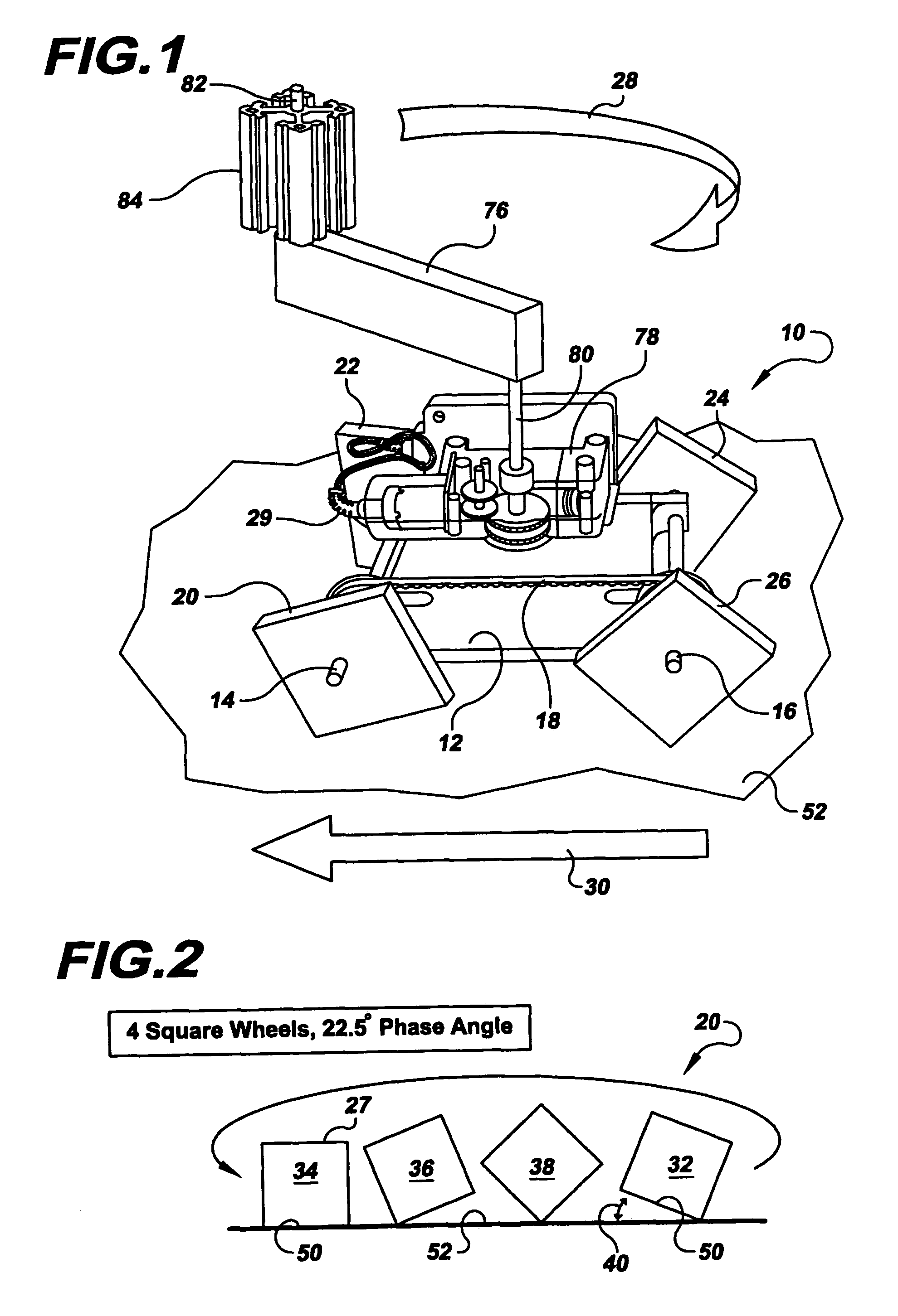
[0030]A first non-circular wheel 20 and a second non-circular wheel 22 are firmly secured to opposed ends of the first axle 14, and a third non-circular wheel 24 and ...


PUM


Abstract

The vehicle (10) includes a frame (12) having at least three non-circular wheels (20, 22, 24) secured to a frame (12), wherein the wheels are mechanically secured to each other so that whenever one non-circular wheel moves, the other wheels (20, 22, 24) move. An offset arm (76) powered by a motor (78) rotates a weight (84) around a geometric center adjacent the wheels to sequentially tip them so that their sequential tipping moves the vehicle (10). The non-circular wheels (20, 22, 24) are sequentially aligned with respect to each other so that whenever one wheel is tipped from a collapse alignment (32) into a contact alignment (34), sequentially the next non-circular wheel (20, 22, 24) is moved into a collapse alignment (32). Any driving force may be used to sequentially tip the non-circular wheels (20, 22, 24, 26), instead of the rotating weight (84).

Description

CROSS REFERENCE TO RELATED APPLICATION[0001]This Application claims the benefit of U.S. Provisional Patent Application Ser. No. 60 / 733,320 that was filed on Nov. 3, 2005, entitled “Vehicle Having A Non-Circular Wheels Propelled By A Moving Weight”.TECHNICAL FIELD[0002]The present invention relates to vehicles and apparatus that move along the ground or a support surface without directly powered wheels, and more particularly relates to a vehicle that propels itself along a support surface by a moving weight or force.BACKGROUND ART[0003]Many efforts are known to produce a vehicle that travels along a support surface such as the ground without applying a rotational force upon wheels of the vehicle in contact with the ground. Such vehicles are sought for a variety of purposes, including the simple novelty, or toy-like entertainment value of an innovative or unusual vehicle, as well as a desire for possibly robotic vehicles to travel over uneven terrain that circular wheels cannot ordina...

Claims


Application Information

Patent Timeline
Patent Type & Authority Patents(United States)
IPC IPC(8): A63H17/00A63H29/00
CPCA63H17/262A63H29/08
Inventor WINCKLER, JASON M.WINCKLER, STEVEN J.
Owner WINCKLER JASON M
Why Eureka
Try Eureka