Reflection lamp
a technology of reflection lamp and lamp body, which is applied in the direction of point-like light source, semiconductor device of light source, light and heating apparatus, etc., can solve the problems of low light efficiency of led and harsh direct light emission to user's eyes, and achieve the effect of easy maintenan
- Summary
- Abstract
- Description
- Claims
- Application Information
AI Technical Summary
Benefits of technology
Problems solved by technology
Method used
Image

Examples
first embodiment
FIG. 2 Shows a First Embodiment
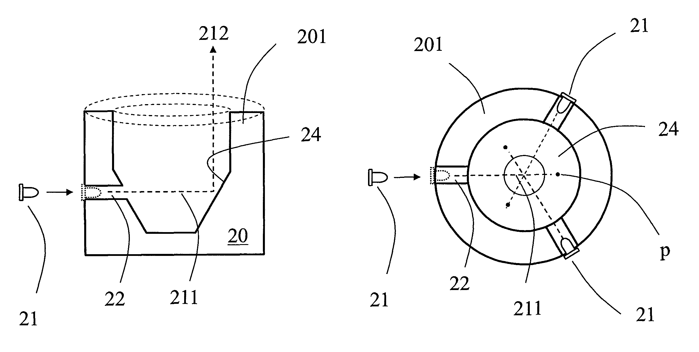
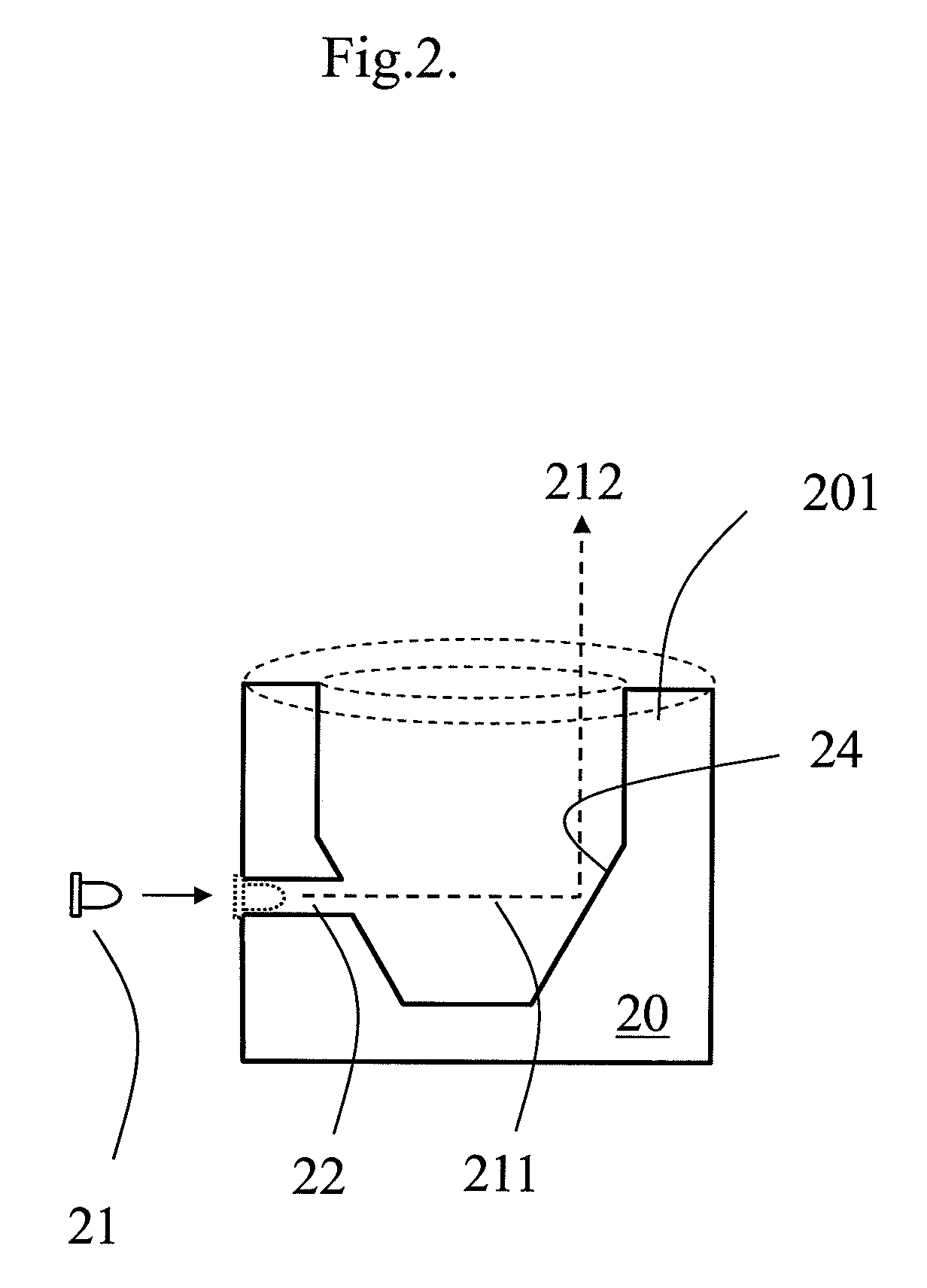
[0013]A Reflection lamp comprises: a metal cup 20 having a cup wall 201; at least a mounting hole 22 is made through the cup wall 201; a light unit 21 is placed inside the mounting hole 22 for emitting a light beam 211; and a reflection surface 24 is arranged in a position opposite to the light unit 21 for reflecting the light beam 211 there from; a reflected light beam 212 comes from the reflection surface 24 and then exits the lamp to form a Reflection lamp. The mounting hole 22 is illustrated to be made through the wall as an example only, it can be a recess on the wall. When the mounting is made through the wall, a failure light unit 21 can be changed easily from outside the lamp.
FIG. 3 Shows a Section View for FIG. 2
[0014]FIG. 3 shows three mounting holes 22, which are made through the cup wall 201, a light unit 21 is placed in each of the mounting holes 22. The light beam 211 emitted from the light unit 21 reaches a reflection surface 24 which is...
second embodiment
FIG. 4 Shows a Second Embodiment
[0015]This design is similar to FIG. 2 but with a D-shaped wall 401. A mounting hole 42 is made through the cup wall 401, a light unit 41 is placed inside the mounting hole 42 for emitting a light beam 411; and a reflection surface 44 is arranged on a position to reflect the light beam 411 from the light unit 41; the light beam 411 is reflected by the reflection surface 44 at point P, a reflected beam 412 then exits the lamp to form a Reflection lamp.
third embodiment
FIG. 5 Shows a Third Embodiment
[0016]A cone reflection surface 54 is placed in a center of the metal cup 50. A mounting hole 52 is made through the cup wall of the metal cup 50 for housing a light unit 51. The light unit 51 emits a light beam 511. The cone reflection surface 54 reflects light beam 511 from the light unit 51; a reflected light beam 512 comes from the reflection surface 54, and exits the lamp to form a Reflection lamp.
PUM
 Abstract
Description
Claims
Application Information
 - R&D
- Intellectual Property
- Life Sciences
- Materials
- Tech Scout
- Unparalleled Data Quality
- Higher Quality Content
- 60% Fewer Hallucinations
Browse by: Latest US Patents, China's latest patents, Technical Efficacy Thesaurus, Application Domain, Technology Topic, Popular Technical Reports.
© 2025 PatSnap. All rights reserved.Legal|Privacy policy|Modern Slavery Act Transparency Statement|Sitemap|About US| Contact US: help@patsnap.com