Striker-fired firearm

a striker-fired, firearm technology, applied in the field of striker-fired firearms, can solve the problems of cumbersome carrying, single pistol grip size may not fit all users' hands, add to the complexity and cost of the firing mechanism of a striker-fired firearm, etc., to increase the vertical spatial relationship and reduce the spatial relationship between the striker and the trigger bar

Active Publication Date: 2010-10-12
STURM RUGER & CO INC
View PDF14 Cites 45 Cited by
  • Summary
  • Abstract
  • Description
  • Claims
  • Application Information

AI Technical Summary

Benefits of technology

[0014]According to another embodiment, a method of operating a striker-fired firearm includes: disposing a trigger bar movably in the firearm; locating a striker in the firearm in a spatial relationship to the trigger bar; engaging the trigger bar with an ejector operable to eject cartridges from the firearm; and using the ejector to change the spatial relationship between the striker and the trigger bar. In one embodiment, the step of using the ejector increases the spatial relationship between the striker and trigger bar. In another embodiment, the step of using the ejector decreases the spatial relationship between the striker and trigger bar. In one embodiment, the spatial relationship change occurs in a vertical direction between the striker and trigger bar. In another embodiment, the step of using the ejector includes camming the trigger bar in a downwards direction to increase a vertical spatial relationship between the striker and trigger bar.

Problems solved by technology

Additional components such as a sear, however, add to the complexity and cost of the firing mechanism for a striker-fired firearm.
Some known mechanisms require the trigger to be pulled to lower and disconnect the trigger bar from the striker which is undesirable.
According to another aspect of general firearm design, pistol and accessory manufacturers have recognized that a single pistol grip size may not fit all users' hands.
Since the extra backstraps are not a permanent part of the pistol, they are cumbersome to carry and may easily be misplaced, lost, or not carried into the field with the user.
In the event that the user desires to change the size of the grip (e.g., to accommodate more than one shooter with different grip size preferences on a given occasion), the extra backstraps may thus simply not be available.

Method used


Image

  • Striker-fired firearm
  • Striker-fired firearm
  • Striker-fired firearm

Examples


Embodiment Construction

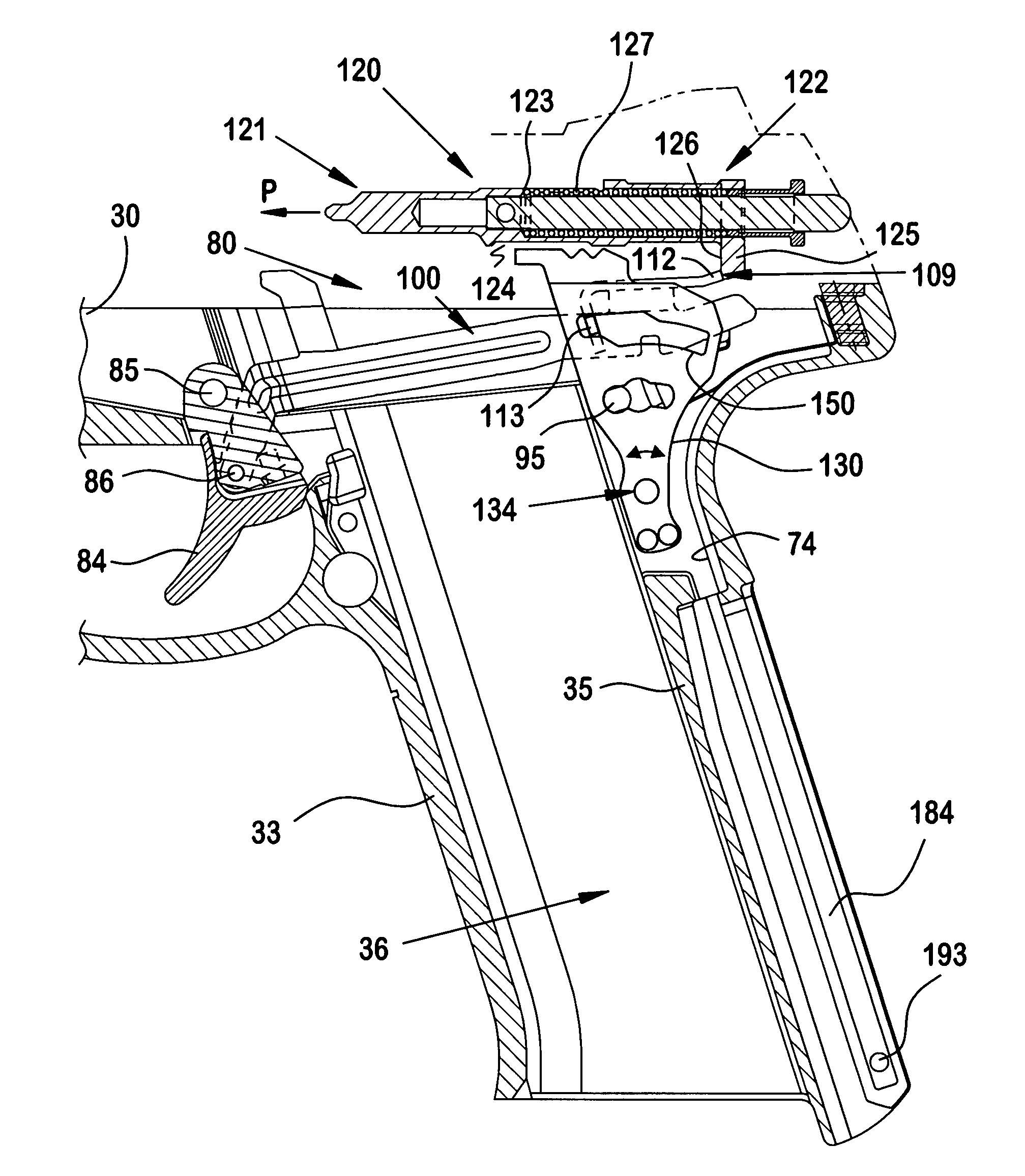
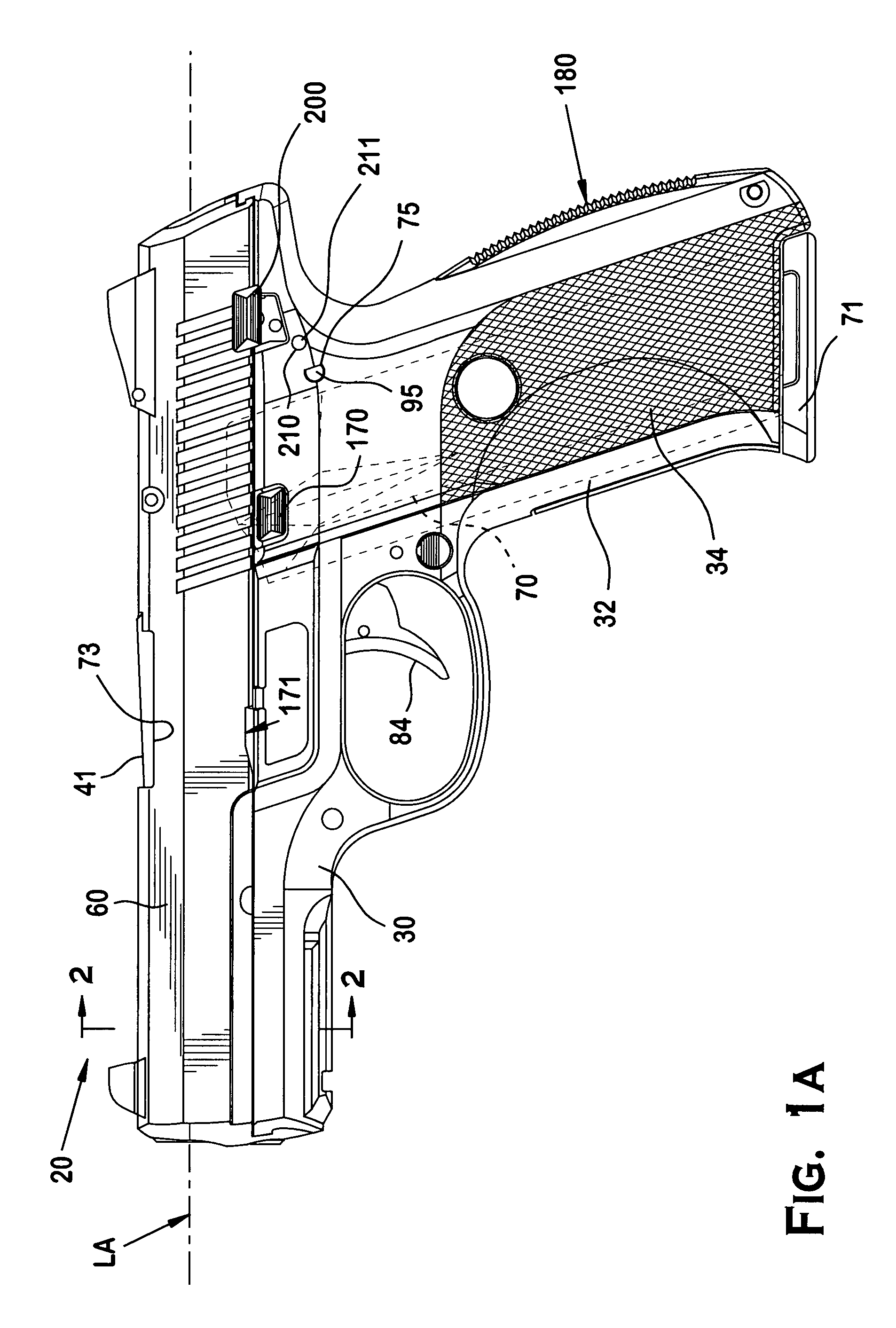
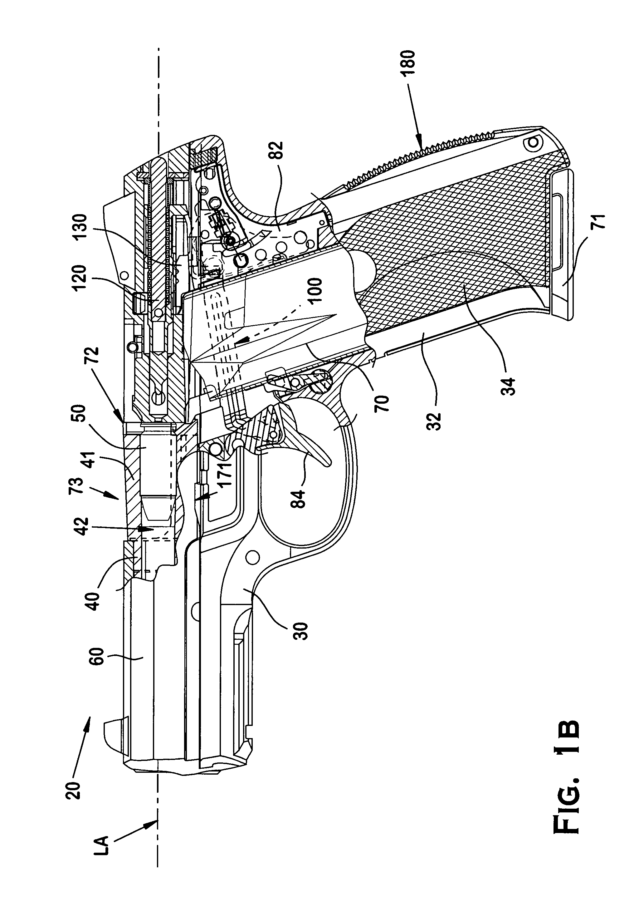
[0056]The features and benefits of the invention are illustrated and described herein by reference to preferred embodiments. This description of preferred embodiments is intended to be read in connection with the accompanying drawings, which are to be considered part of the entire written description. In the description of embodiments disclosed herein, any reference to direction or orientation is merely intended for convenience of description and is not intended in any way to limit the scope of the present invention. Relative terms such as “lower,”“upper,”“horizontal,”“vertical,”, “above,”“below,”“up,”“down,”“top” and “bottom” as well as derivative thereof (e.g., “horizontally,”“downwardly,”“upwardly,” etc.) should be construed to refer to the orientation as then described or as shown in the drawing under discussion. These relative terms are for convenience of description only and do not require that the apparatus be constructed or operated in a particular orientation. Terms such as...


PUM

PropertyMeasurementUnit
sizeaaaaaaaaaa
sizesaaaaaaaaaa
areaaaaaaaaaaa

Abstract

A striker-fired firearm with field stripping mechanism and method. A striker-fired firearm generally includes a frame, a slide supported by the frame for longitudinal forward and rearward movement, a striker axially movable in a path of travel along a longitudinal axis, a trigger pivotably connected to the frame, a trigger bar movably coupled to the trigger and adapted to engage the striker, and a trigger bar camming member pivotably disposed in the frame and defining a camming surface engaged by the trigger bar. Pivoting the camming member moves the trigger bar from a first position to a second position in spatial relationship to the striker. In a preferred embodiment, the camming member is an ejector operable to expel spent cartridge casings from the firearm.

Description

BACKGROUND OF THE INVENTION[0001]The present invention generally relates to firearms, and more particularly to striker-fired firearms and associated firing control mechanisms.[0002]Firearms such as semi-automatic pistols generally include a frame, a barrel that defines a chamber for holding a cartridge, a reciprocating slide that defines a breech face on the front for engaging the rear of the chamber; and a spring-loaded axially-movable firing pin disposed in the slide that contacts the cartridge to discharge the pistol. When the pistol is discharged, the slide recoils rearward with respect to the frame and then returns forward to open and close the action. There are various design approaches to firing control mechanisms for striking the cartridge with the firing pin.[0003]One type of firearm has a firing control mechanism that cocks and releases a hammer via a trigger pull to strike the firing pin. The firing pin is driven forward by the hammer and contacts the cartridge. Another t...

Claims


Application Information

Patent Timeline
Patent Type & Authority Patents(United States)
IPC IPC(8): F41A17/00
CPCF41A11/00F41A15/16F41A17/02F41A17/56F41A35/06F41C23/10F41C23/14F41A19/35Y10T29/49815
Inventor MCGARRY, JAMES
Owner STURM RUGER & CO INC
Why Eureka
Try Eureka