
Sound pressure level feedback control

a feedback control and sound pressure technology, applied in water supply installation, process and machine control, instruments, etc., can solve the problems of inability to detect and control and inability to detect the external noise level

Active Publication Date: 2010-10-19
FISHER CONTROLS INT LLC
View PDF15 Cites 18 Cited by
  • Summary
  • Abstract
  • Description
  • Claims
  • Application Information

AI Technical Summary

Problems solved by technology

In particular, aerodynamic noise that may be generated by control valves and propagate downstream in piping may lead to unacceptable external noise levels.
Some of the process conditions that are typically set upstream and downstream of the control valve are pressures and mass or volumetric flow rates, with the conditions downstream of the control valve being susceptible to creating undesirable noise radiating from the pipeline.
However, such arrangements can be expensive to install and maintain, thereby adding to the cost of an overall process control system.
Use of free field microphones and pressure transducers can be problematic in some situations, due to the cost and complexity of installing such devices.
The IEC standard has procedures that are specifically tailored to control valve noise based on transmission loss at a single frequency, and are unsuitable for more general predictions of piping system noise.
The transmission loss is a function of frequency and not just the peak frequency, so the IEC method will be limited when one is concerned with a frequency range.

Method used


Image

  • Sound pressure level feedback control
  • Sound pressure level feedback control
  • Sound pressure level feedback control

Examples


Embodiment Construction

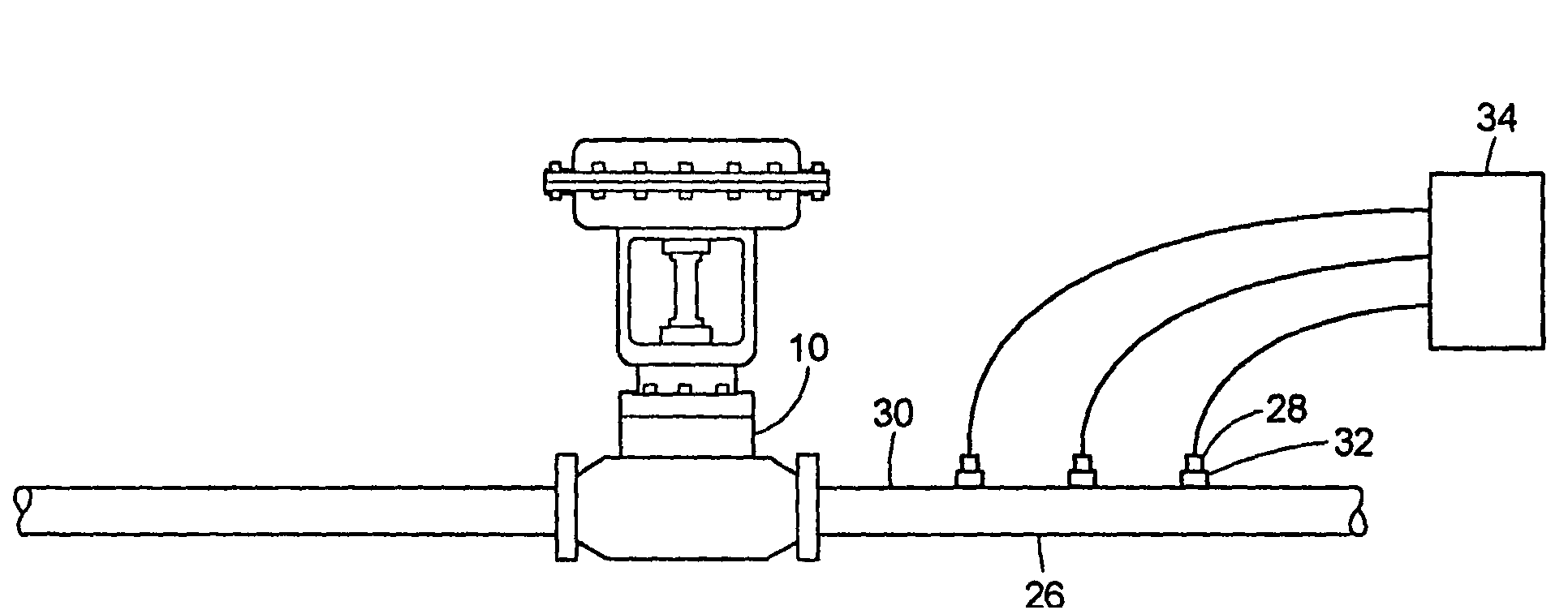
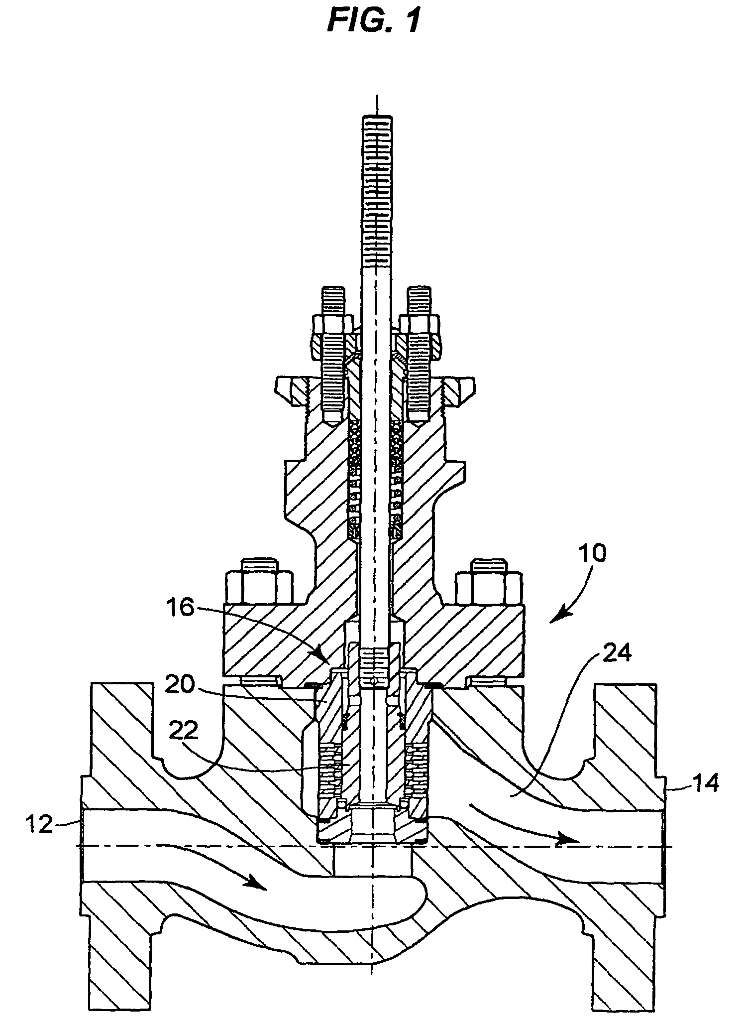
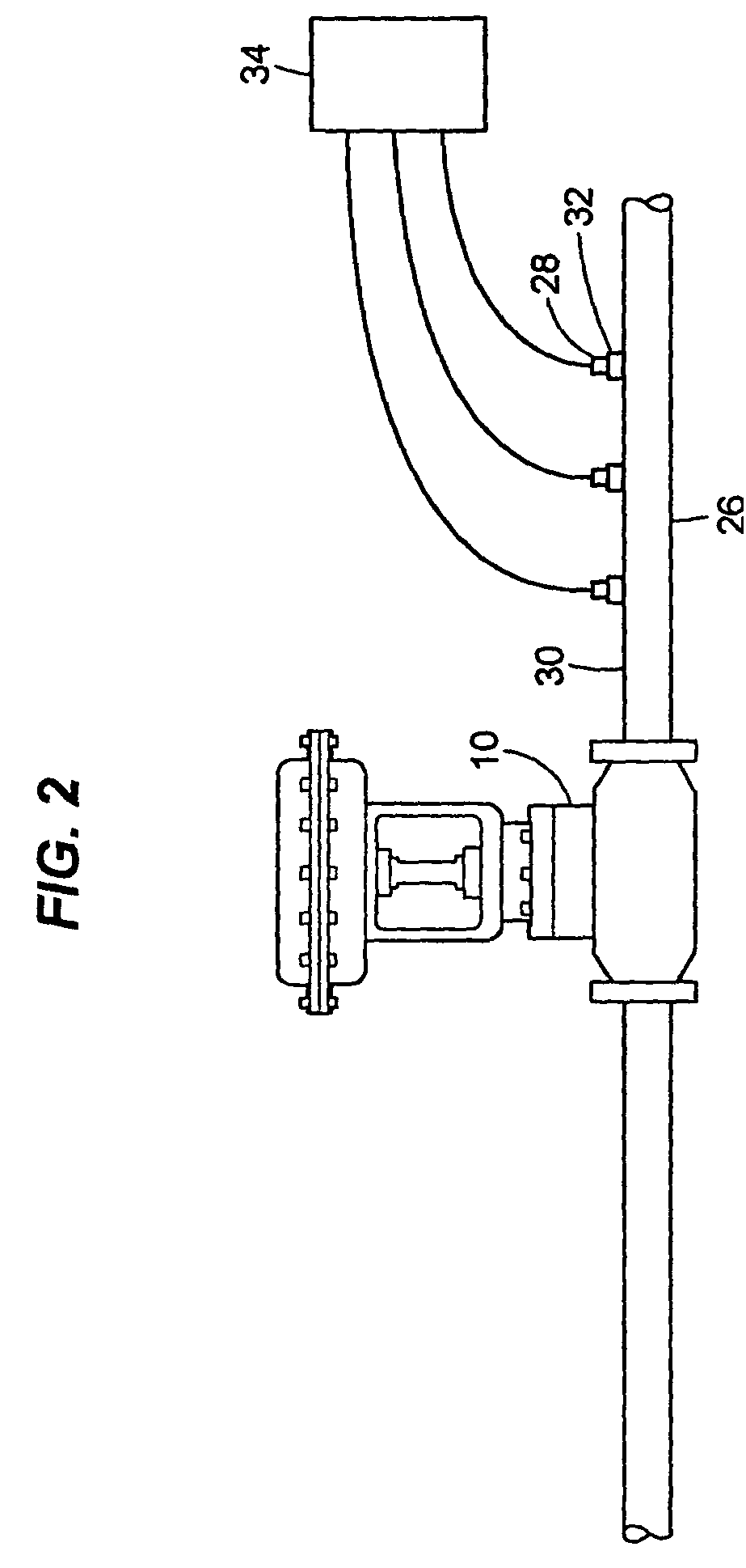
[0022]A cross-sectional side view of a typical globe style control valve 10 is shown in FIG. 1, with arrows showing a typical path fluid would take through the control valve 10 in a process control system (shown in FIG. 2), entering at an inlet portion 12 and exiting at an outlet portion 14. The control valve 10 may contain a cage and plug assembly 16 in an interior cavity 24 containing a cage 20 and a plug 22. The plug 22 resides inside of the cage 20 with the outside diameter of the plug 22 and inside diameter of the cage 20 providing the guiding and the shut off capability. It is generally understood that the globe style control valve 10 in FIG. 1 will permit no flow if the valve plug 22 is in a fully closed position. Alternatively, when the valve plug 22 is in a fully opened position, the control valve 10 will have the maximum open area available to the flowing medium providing the maximum flow rate through the cage and plug assembly 16, and subsequently, will have a minimum pre...


PUM


Abstract

Methods and systems are provided for predicting internal sound pressure within a flow passage, by measuring a vibration velocity response of a wall of the flow passage, for example, using accelerometers. A radiation model may then be used for predicting externally radiated sound pressure to provide feedback to control a process control system. Methods and systems are also provided for predicting externally radiated sound pressure based on internally-mounted pressure transducer sensor data.

Description

CROSS-REFERENCE TO RELATED APPLICATIONS[0001]This application claims the benefit under 35 U.S.C. §119(e) of U.S. provisional patent application Ser. No. 60 / 737,522, filed Nov. 16, 2005, the entire disclosure of which is incorporated herein by reference.FIELD OF THE DISCLOSURE[0002]The present disclosure is generally related to prediction of sound pressure levels in process control systems, and is specifically related to prediction of sound pressure levels inside flow passages and / or surrounding the flow passages, such as, for example, steel pipes, due to gaseous fluid flow within the pipes to control the process control system.BACKGROUND[0003]In process control systems, such as, for example, pipelines, that carry gaseous fluids, such as, for example compressed air, it is often useful to determine internal sound pressure levels. Internal sound pressure levels may be used to make transmission loss predictions, and can therefore help in the design and operation of pipelines and other p...

Claims


Application Information

Patent Timeline
Patent Type & Authority Patents(United States)
IPC IPC(8): F16K31/02
CPCG05D7/0635Y10T137/0324Y10T137/2196Y10T137/7761
Inventor CATRON, FREDERICK WAYNE
Owner FISHER CONTROLS INT LLC
Learn More