Vehicle-purpose lighting tool

a technology for vehicles and lighting tools, applied in semiconductor devices for light sources, light and heating apparatus, transportation and packaging, etc., can solve the problem that the presence of led lamps is practically difficult to be completely concealed, and achieve the effect of effective avoidance, increased deep depth feelings, and higher design characteristics

Inactive Publication Date: 2010-10-19
TOYODA GOSEI CO LTD
View PDF4 Cites 14 Cited by
  • Summary
  • Abstract
  • Description
  • Claims
  • Application Information

AI Technical Summary

Benefits of technology

[0007]As a consequence, the present invention has an object to provide a vehicle-purpose lighting tool having a high design characteristic and capable of avoiding that a light source is directly and visually recognizable.
[0013]In the above-described structure, such a light that is directly traveled to the side edge plane of the light-conducting member is totally reflected among the external light which is entered via the front light-emitting plane into the light-conducting member. Since the external light is totally reflected in the above-described manner, the light source can be hardly and visually recognized through the front light-emitting plane of the light-conducting member. In other words, it is possible to effectively avoid that the light source is directly and visually recognized through the front light-emitting plane of the light-conducting member.
[0014]On the other hand, the reflecting portions are arrayed via the coupling portion in the direction along which the reflecting portions are separated from the side edge plane in such a manner that the distances between these reflecting portions and the front light-emitting plane are changed in the discontinuous manner. As a result, a thicker thickness portion of the light-conducting member is located adjacent to a thinner thickness portion thereof. As a consequence, when the light-conducting member is observed from the front plane thereof, a difference between the thicknesses of the light-conducting member is emphasized, so that deep depth feelings may be increased. As a result, a higher design characteristic may be achieved. Also, a space portion is formed of the concave / convex portions of the rear plane of the light-conducting member, so that the incident light passes through this space portion to be traveled, and then, the traveled light is entered into the reflecting portions positioned apart from the light source. Since a sufficiently large amount of the light is also entered into the reflecting portions positioned apart from the light source, luminance of light that is emitted from the front light-emitting plane is made uniform, and the light can be effectively utilized.

Problems solved by technology

Accordingly, even when the above-explained measures have been taken, it is practically difficult that the presence of these LED lamps is completely concealed.

Method used


Image

  • Vehicle-purpose lighting tool
  • Vehicle-purpose lighting tool
  • Vehicle-purpose lighting tool

Examples


embodiment 1

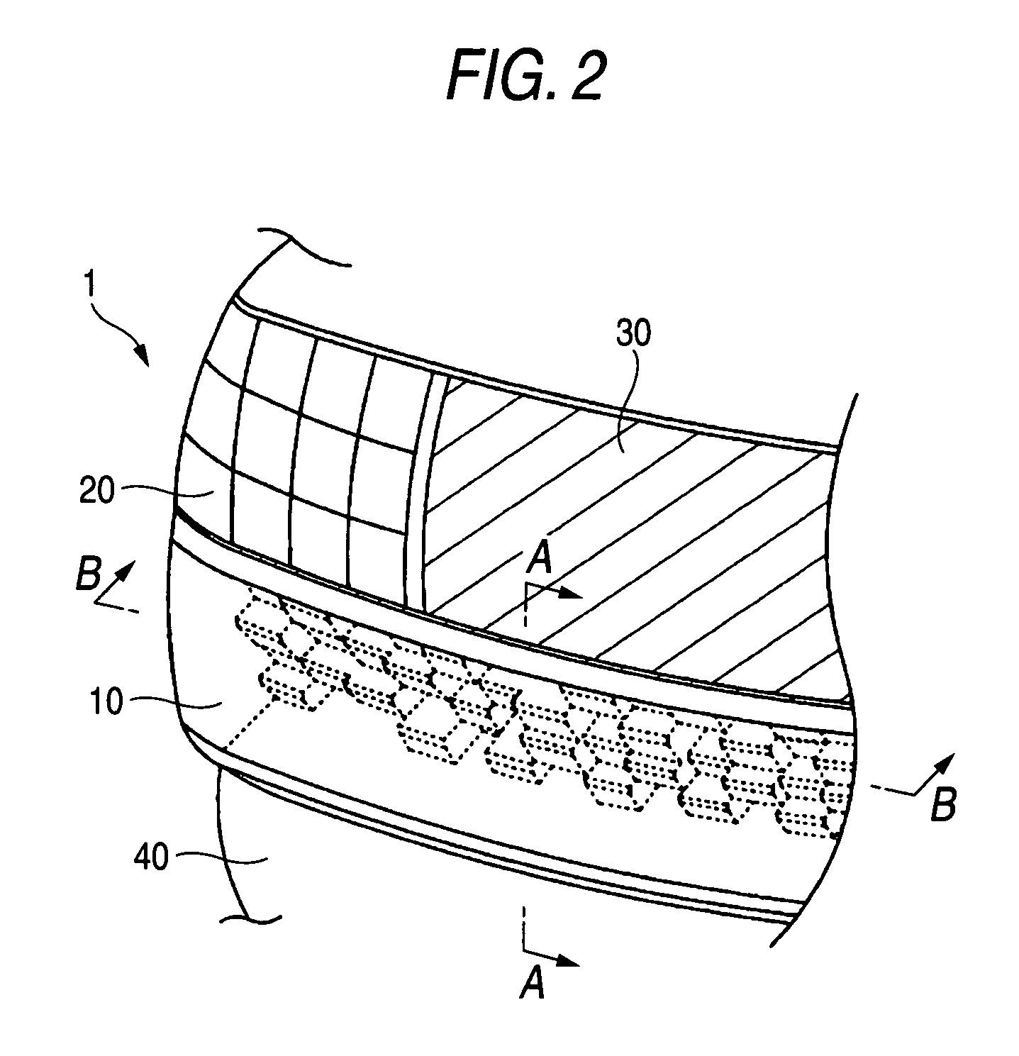
[0036]FIG. 2 is a perspective view for indicating a rear combination lamp 1 corresponding to an embodiment 1 of a vehicle-purpose lighting tool according to the present invention. The Rear combination lamp 1 is constituted of a tail / stop lamp unit 10 for performing a tail lamp indication and a stop lamp indication; a turn lamp unit 20 for performing a turn lamp indication; and a back lamp unit 30 for performing a back lamp indication.

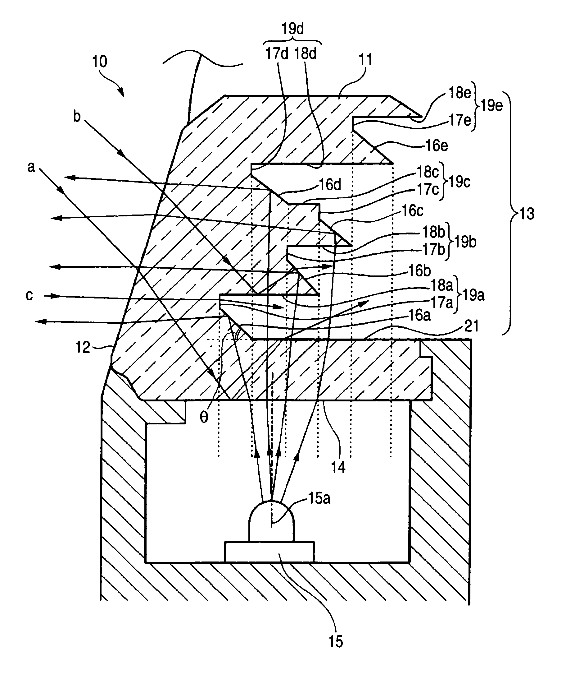
[0037]FIG. 3 is a sectional view for showing the rear combination lamp 1, taken along a line A-A indicated FIG. 2. FIG. 4 is a sectional view for representing the rear combination lamp 1, taken along a line B-B indicated in FIG. 2. As shown in FIG. 3, the tail / stop lamp unit 10 is equipped with a light-conducting member 11, and an LED (light-emitting diode) lamp 15. The light-conducting member 11 is made of an acrylic resin, and a refractive index thereof is approximately 1.5. A color of the LED lamp 15 belongs to a red color series, and this LED lamp 1...


PUM


Abstract

A vehicle-purpose lighting tool is featured by comprising: a light-conducting member having a front light-emitting plane, a rear plane having a concave / convex shape, and a side edge plane; and a light source arranged at a position opposite to the side edge plane; in which within external light which is entered via the front light-emitting plane into the light-conducting member, a portion of the external light which is directly traveled to the side edge plane is totally reflected on a boundary plane of the side edge plane portion; a plurality of reflecting portions are formed on the rear plane and are coupled to each other via a coupling portion in such a direction that the reflecting portions are separated apart from the side edge plane side; and distances between the plurality of reflecting portions and the front light-emitting plane are changed in a discontinuous manner along the separating direction.

Description

BACKGROUND OF THE INVENTION[0001]1. Field of the Invention[0002]The present invention is related to a vehicle-purpose lighting tool. More specifically, the present invention is directed to an improvement of such vehicle-purpose lighting tools as rear combination lamps.[0003]2. Description of the Related Art[0004]In vehicle-purpose lighting tools such as rear combination lamps and high-mounted stop lamps, light of light sources is radiated outside the light sources via outer lenses (designed covers) so as to obtain desirable light emissions. For instance, as indicated in FIG. 8, in a rear combination lamp where LED lamps 102 are employed as light sources, the LED lamps 102 are installed inside an outer lens 101, and reflectors 103 are provided at peripheral portions of the LED lamps 102 (refer to, for instance, patent publication 1). In the above-described structure, light of the LED lamps 102 is directly traveled to the forward direction, or is traveled via the reflectors 103, and t...

Claims


Application Information

Patent Timeline
Patent Type & Authority Patents(United States)
IPC IPC(8): F21V5/00
CPCB60Q1/2696F21S48/215F21S48/2237F21S48/225F21S48/2281F21S48/236F21V7/0091F21Y2101/02F21Y2115/10F21S43/14F21S43/237F21S43/241F21S43/249F21S43/315
Inventor MISAWA, AKIHIROARAKAWA, TETSUYAOBA, TATSUYAISHIKAWA, AKIHIKO
Owner TOYODA GOSEI CO LTD
Why Eureka
Try Eureka