
Lighting device for vehicle

a technology for lighting devices and vehicles, applied in lighting and heating equipment, instruments, transportation and packaging, etc., can solve the problems of deterioration of design characteristics and lack of study of cooling structure, and achieve the effects of efficient cooling by outside air, simple structure and efficient cooling operation

Inactive Publication Date: 2011-02-08
TOYODA GOSEI CO LTD
View PDF16 Cites 12 Cited by
  • Summary
  • Abstract
  • Description
  • Claims
  • Application Information

AI Technical Summary

Benefits of technology

As described above, according to the structure of the present invention, the lighting device having high design characteristics can be obtained irrespective of a simple structure.
In the rear combination lamp of the present invention, the first vent hole functions as an exhaust hole and the second vent hole functions as an air inlet hole. That is, in the housing, a flow of air is generated from the second vent hole to the first vent hole. Thus, the first lamp and the second lamp are cooled. Here, the tail / stop lamp part whose frequency of use is high is arranged in an upper part, so that air heated by the tail / stop lamp part is rapidly discharged to an external part from the first vent hole in the vicinity of the first lamp. Thus, the housing is not filled with heat and is efficiently cooled by outside air. As described above, according to the structure of the present invention, since the frequency of use of the lamp is taken into consideration, an efficient cooling operation is carried out in spite of a simple structure.

Problems solved by technology

Further, when the lighting device is lighted, the edge part as the welding part does not emit light, which results in the deterioration of the design characteristics.
However, such a cooling structure is not especially studied.

Method used


Image

  • Lighting device for vehicle
  • Lighting device for vehicle
  • Lighting device for vehicle

Examples


embodiment 1

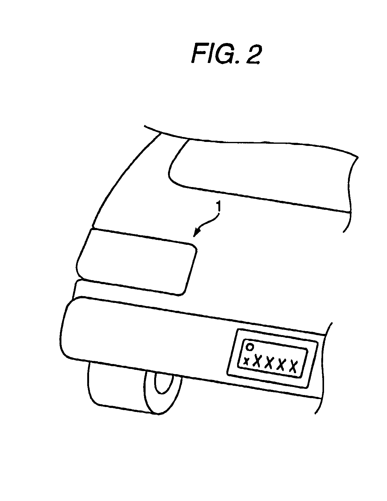
Now, the structure of the present invention will be described in more detail by employing an embodiment 1. FIG. 2 is a perspective view showing a rear part of a motor vehicle provided with a rear combination lamp 1 of the embodiment 1. FIG. 3 is a front view of the rear combination lamp 1. FIG. 4 is a sectional view taken along a line A-A of FIG. 3. The rear combination lamp 1 includes a tail / stop lamp part 10 for carrying out a tail lamp display and a stop lamp display and a turn lamp part 20 for carrying out a turn signal display.

As shown in FIG. 4, the rear combination lamp is roughly classified into and includes a lens 30, two kinds of LED units (a first LED unit 40 and a second LED unit 45) and a housing 50. In the rear combination lamp 1, an outer part is directly irradiated with light emitted from the front surface 31 of the lens 30. That is, the front surface 31 of the lens 30 is a designed surface of the rear combination lamp 1. Thus, a peculiar sense of three dimensions an...

embodiment 2

FIG. 7 is a perspective view showing a rear part of a motor vehicle provided with a rear combination lamp 201 of an embodiment 2 of the present invention. FIG. 8 is a front view of the rear combination lamp 201. FIG. 9 is a sectional view taken along a line A-A of FIG. 8. The rear combination lamp 201 includes a tail / stop lamp part 210 for carrying out a tail lamp display and a stop lamp display and a turn lamp part 220 for carrying out a turn signal display.

As shown in FIG. 9, the rear combination lamp 201 is roughly classified into and includes a lens 230, two kinds of LED units (a first lamp 240 and a second lamp 245) and a housing 250. In the rear combination lamp 201, an outer part is directly irradiated with light emitted from the front surface 231 of the lens 230. That is, the front surface 231 of the lens 230 is a designed surface of the rear combination lamp 201. Thus, a peculiar sense of three dimensions and crystal is obtained.

The housing 250 is made of a synthetic resin ...

embodiment 3

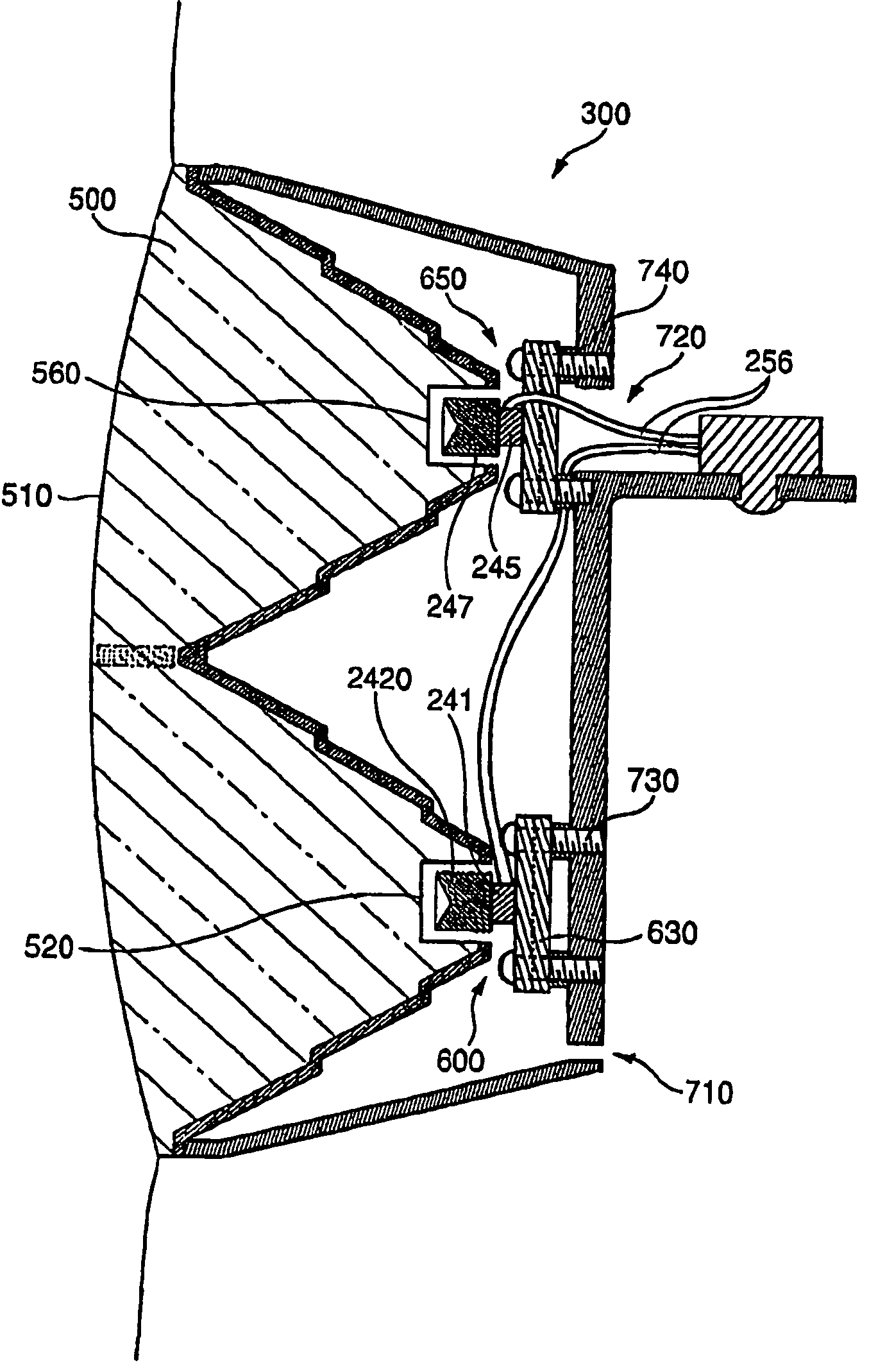
FIG. 13 shows a front view of a rear combination lamp 300 of another embodiment of the present invention. FIG. 14 is a sectional view taken along a line B-B in FIG. 13. Members the same as those of the rear combination lamp 201 are designated by the same reference numerals and an explanation thereof will be omitted.

As shown in FIG. 14, the rear combination lamp 300 is roughly classified into and includes a lens 500, two kinds of LED lamps (a first lamp 600 and a second lamp 245) and a housing 700. In the rear combination lamp 300, an outer part is directly irradiated with light emitted from the front surface 510 of the lens 500. That is, the front surface 510 of the lens 500 is a designed surface of the rear combination lamp 300. Thus, a peculiar sense of three dimensions and crystal is obtained. The rear combination lamp 300 has a structure that positively shows the first lamp 600 and the second lamp 245 in the designed surface (the front surface 510).

The housing 700 is made of a s...


PUM


Abstract

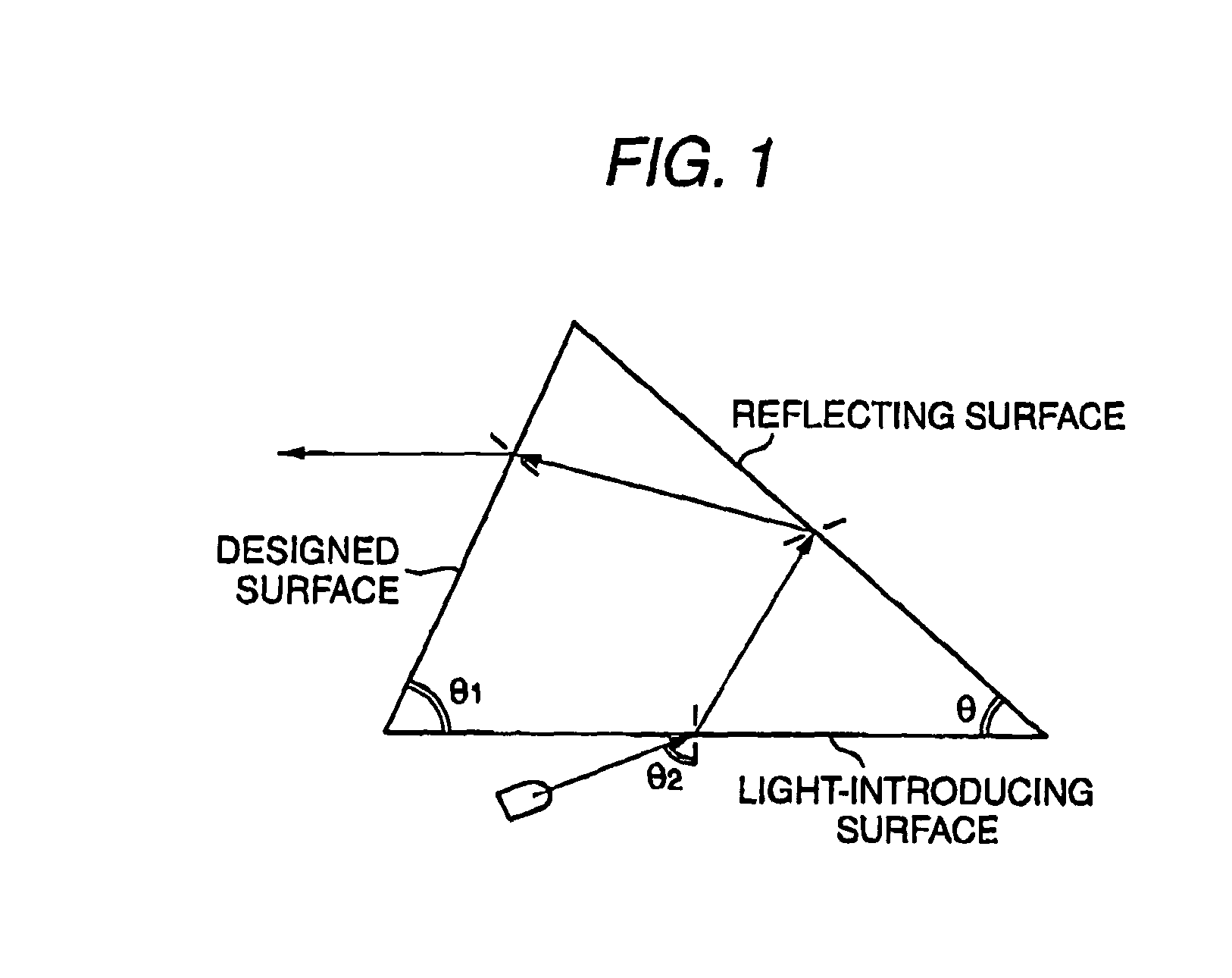
A lighting device for a vehicle includes: a light source; a light guide member that has a light-introducing part provided in a back surface side through which the light of the light source is introduced and finally emits the light from a front surface side; a part near the light-introducing part being thicker than an edge part of the light guide member, a plurality of reflecting parts and connecting parts being alternately formed continuously toward a direction separate from the light-introducing part in the back surface side, the reflecting parts respectively reflecting on interfaces the introduced light reaching there to form the light in the direction of the front surface of the light guide member; and a housing that is connected to a position between the edge part of the back surface of the light guide member and the light-introducing part and attached to the back surface side of the light guide member to house the light source.

Description

BACKGROUND OF THE INVENTION1. Field of the InventionThe present invention relates to a lighting device for a vehicle. More particularly, the present invention relates to an improvement of a lighting device for a vehicle such as a rear combination lamp.2. Description of the Related ArtUsually, in the lighting device for a vehicle such as a rear combination lamp or a high mount stop lamp, the light of a light source is externally emitted through an outer lens (a designed cover) to obtain a desired light emission. For instance, as shown in FIG. 15(a), a lamp 1102 is disposed inside the outer lens 1101 and a reflector 1103 is provided in the periphery of the lamp 1102 (for instance, see JP-A-2005-123092). In such a structure, the light of the lamp 1102 directly advances or advances forward through the reflector 1103 and is emitted outside through the outer lens 1101.In the above-described usual lighting device, the outer lens 1101 needs to be connected to a housing 1104 in view of a wat...

Claims


Application Information

Patent Timeline
Patent Type & Authority Patents(United States)
IPC IPC(8): F21V8/00
CPCB60Q1/0088B60Q1/2607B60Q1/2696F21S48/215F21S48/2237F21S48/2268F21S48/2287F21S48/23F21S48/337F21V7/0091F21S43/14F21S43/237F21S43/245F21S43/247F21S43/30F21S45/37
Inventor TOTANI, CHIHARUMISAWA, AKIHIROOBA, TATSUYAARAKAWA, TETSUYAWATANABE, SHINYA
Owner TOYODA GOSEI CO LTD
Learn More