
Heating cooker

a technology for cooking and cooking surfaces, applied in the field of cooking cookers, can solve the problems of difficult viewing angle of displayed contents, and achieve the effects of wider visible angle, higher luminance, and easy viewing of displayed contents

Inactive Publication Date: 2011-12-06
IRIS OHYAMA
View PDF22 Cites 0 Cited by
  • Summary
  • Abstract
  • Description
  • Claims
  • Application Information

AI Technical Summary

Benefits of technology

The invention is a heating cooker with a liquid crystal display that can be difficult to view from an angle and has a non-displayed portion that degrades its appearance. The invention solves this problem by providing a heating cooker with a translucent top plate and a fluorescent display tube underneath it. This allows the user to easily view the displayed content and makes the non-displayed portion less visible, improving the appearance of the cooker.

Problems solved by technology

However, although the liquid crystal display is illuminated by the backlight, a view angle (an angle within which the contents can be viewed) is narrow, and the displayed contents are difficult to view from an angle.

Method used


Image

  • Heating cooker
  • Heating cooker
  • Heating cooker

Examples


first embodiment

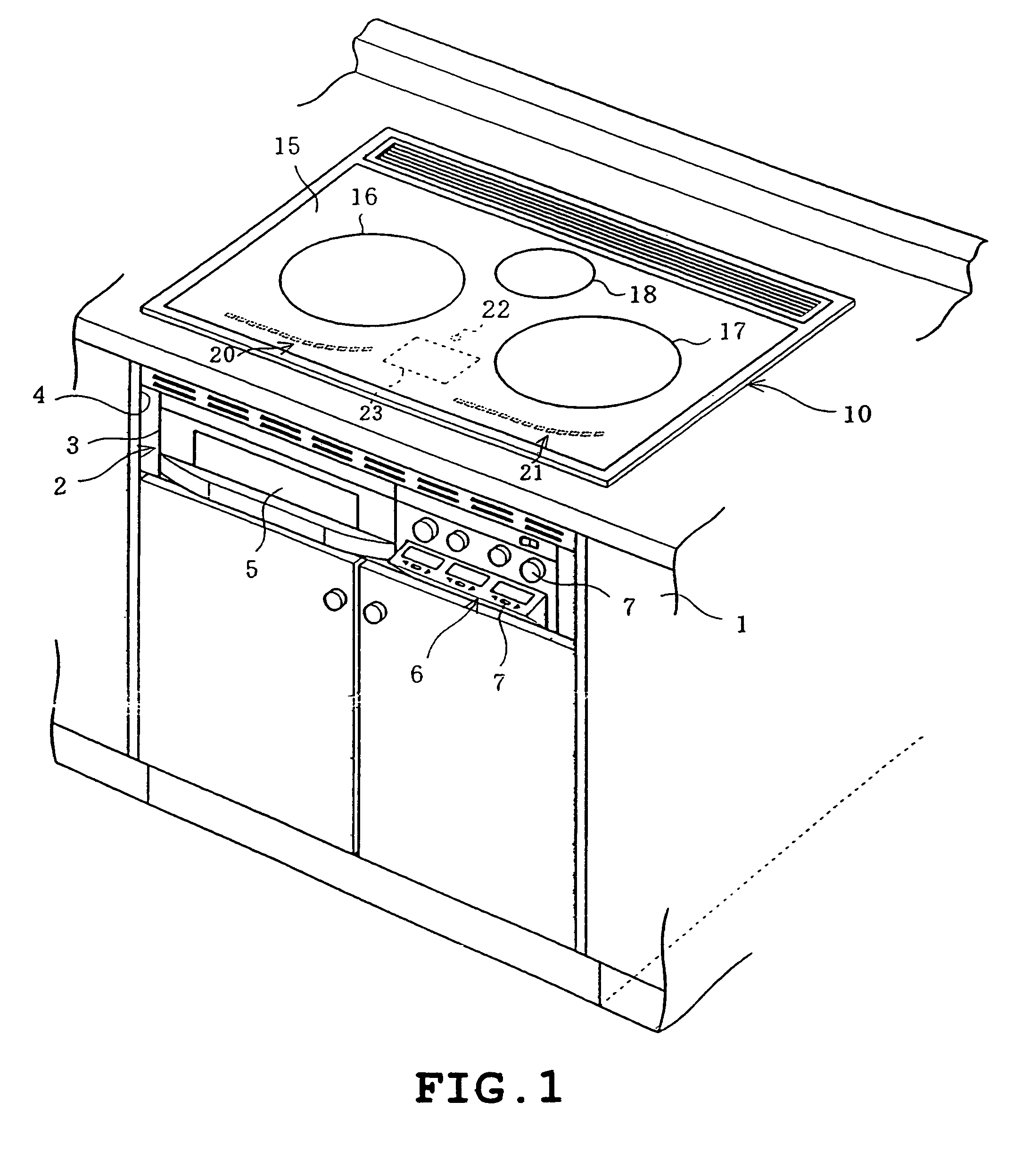
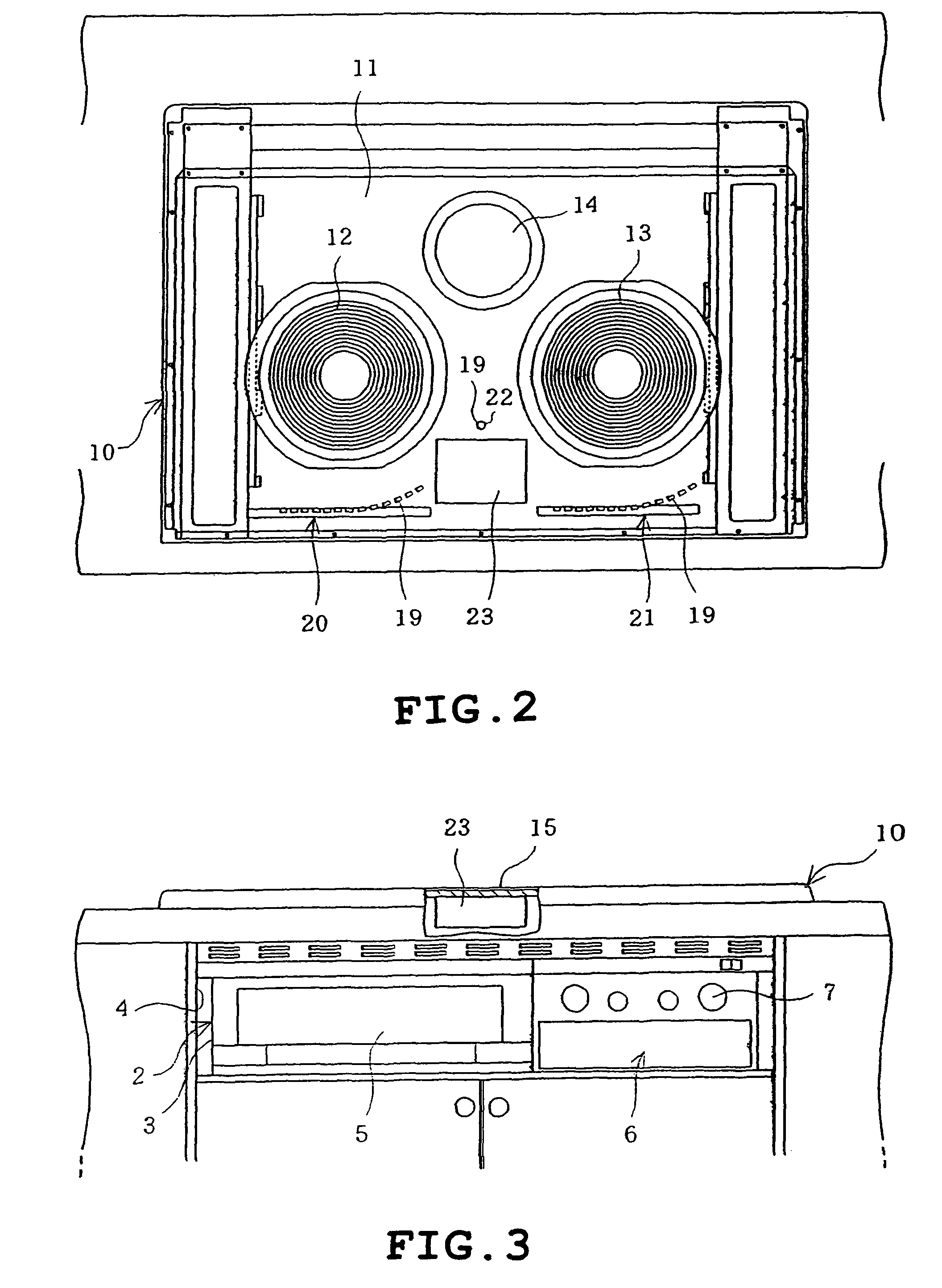
[0024]FIGS. 1 to 5 illustrate the invention. Firstly, FIG. 1 shows a kitchen cabinet in which a heating cooker 2 is built. In FIG. 1, a body 3 of the heating cooker 2 is housed in a housing 4 provided in the cabinet 1. A roaster 5 is provided in the left of the body 3 whereas an operating portion 6 is provided in the right of the body 3. The operating portion 6 is provided with a plurality of switches 7.

[0025]An upper heating unit 10 as shown in FIG. 2 is provided on the top of the body 3. The upper heating unit 10 includes a rectangular box-shaped upper case 11 with an upper opening, left and right heating coils 12 and 13 both for induction heating disposed left and right in the upper case 11 and a central heater 14 comprising a radiant heater, for example, located at a central rear side. The upper heating unit 10 has an upper opening closed by a top plate 15 which is made from heat-resistant glass and disposed to cover the heating coils 12 and 13 and the heater 14 from above.

[0026...

second embodiment

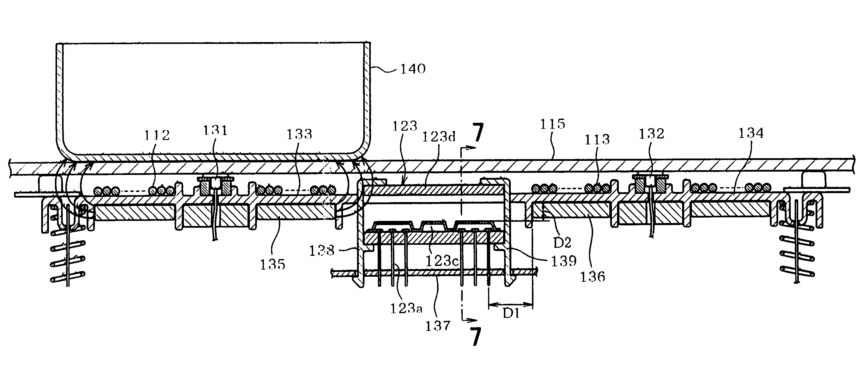
[0040]FIGS. 6 to 11 illustrate the invention. Firstly, FIG. 9 is a perspective view showing an appearance of the heating cooker 102 built in the cabinet 101 of the kitchen. FIG. 10 is a plan view of the major part of the heating cooker 102 with the top plate being removed. The body 103 of the heating cooker 102 is housed in a housing 104 provided in the cabinet 101. A roaster 105 is provided in the left of the body 103 whereas an operating portion 106 is provided in the right of the body 103. The operating portion 106 is provided with a plurality of switches 107.

[0041]An upper heating unit 110 as shown in FIG. 10 is provided on the top of the body 103. The upper heating unit 110 includes a rectangular box-shaped upper case 111 with an upper opening, left and right heating coils 112 and 113 both for induction heating disposed left and right in the upper case 111 and a central heater 114 comprising a radiant heater, for example, located at a central rear side. The upper heating unit 1...


PUM


Abstract

In a heating cooker, an object to be heated is placed on a top plate and is heated by a heating unit located below the top plate. The top plate is translucent and a fluorescent display tube is located below the top plate. The top plate is configured to have spectral transmission characteristics in a visible light range such that the spectral transmission at a wavelength of approximately 500 nm corresponding to blue or green is substantially one third of a spectral transmission at a wavelength of approximately 700 nm corresponding to red such that the spectral transmission is gradually rendered larger as the wavelength is increased from approximately 500 nm to approximately 700 nm.

Description

[0001]This application is a continuation of PCT / JP2005 / 007080, filed Apr. 12, 2005, which claims the benefit of priority of Japanese Application No. 2004-139818, filed May 10, 2004 and Japanese Application No. 2004-179958, filed Jun. 17, 2004, the contents of all which are incorporated herein by reference.TECHNICAL FIELD[0002]The present invention relates to a heating cooker constructed to heat a heated object placed on a top plate by a heating unit provided below the top plate.BACKGROUND ART[0003]As this type of heating cooker, for example, an induction heating cooker is known in which a liquid crystal display is provided below the top plate and a backlight is provided in the rear of the liquid crystal display so that on-off state of a heating coil serving as a heating unit, an input power level and the like are displayed by the liquid crystal display (see patent documents 1 and 2, for example). In this construction, a portion of the top plate corresponding to the liquid crystal di...

Claims


Application Information

Patent Timeline
Patent Type & Authority Patents(United States)
IPC IPC(8): H05B3/58H05B6/02H05B6/12
CPCH05B6/1218Y02B40/123Y02B40/00H05B6/12F24C7/082
Inventor IMAMOTO, KAZUNARIESAKI, TAKESHIKONDO, MASAOMATSUO, KATSUHARU
Owner IRIS OHYAMA
Learn More