Image forming apparatus, control method therefor, and program

a technology of image forming apparatus and control method, which is applied in the direction of electrographic process apparatus, instruments, optics, etc., can solve the problems of increasing the burden (of) users, the size of the detecting unit or the cost and the inability to resolve the setting mistake or accidental omission setting, etc., to achieve the effect of improving the reliability of the image forming apparatus and reducing the life cos

Inactive Publication Date: 2010-10-19
CANON KK
View PDF8 Cites 0 Cited by
  • Summary
  • Abstract
  • Description
  • Claims
  • Application Information

AI Technical Summary

Benefits of technology

[0009]An embodiment of the present invention provides an image forming apparatus, a control method therefor, and a program that can serve to contemplate improvement of the reliability of the image forming apparatus and reduction of life cost charged to a user of the image forming apparatus.
[0011]According to an embodiment of the present invention, image forming control based on the determined type of paper is performed, thereby allowing for resolving wrong setting of paper in use or a problem such as growth in size or increase of cost of a unit for detecting physical properties of paper. This makes it possible to contemplate improvement of the reliability of the image forming apparatus and reduction of life cost charged to a user of the image forming apparatus.

Problems solved by technology

However, in the above conventional examples, a burden on (effort for) a user increases if the user is required to set the type of transfer paper used in an image forming apparatus.
This makes it difficult to resolve setting mistake or accidental omission of setting.
Additionally, if an image forming apparatus employs a detecting unit that directly detects physical properties of the transfer paper as numerical values in an electrical or mechanical manner, a problem may arise concerning a size of the detecting unit or cost increase of the image forming apparatus.
Furthermore, the conventional image forming apparatus may not accurately estimate appropriate working life of a component (time to replace the component) since the conventional apparatus does not consider that the life of a component will change that is installed in the image forming apparatus according to the type of transfer paper used.
Because of this, replacement of a component not exceeding its working life causes a burden of extra cost to a user or continuous use of the component exceeding its working life induces a problem such as paper jam or a defective image.

Method used


Image

  • Image forming apparatus, control method therefor, and program
  • Image forming apparatus, control method therefor, and program
  • Image forming apparatus, control method therefor, and program

Examples


first embodiment

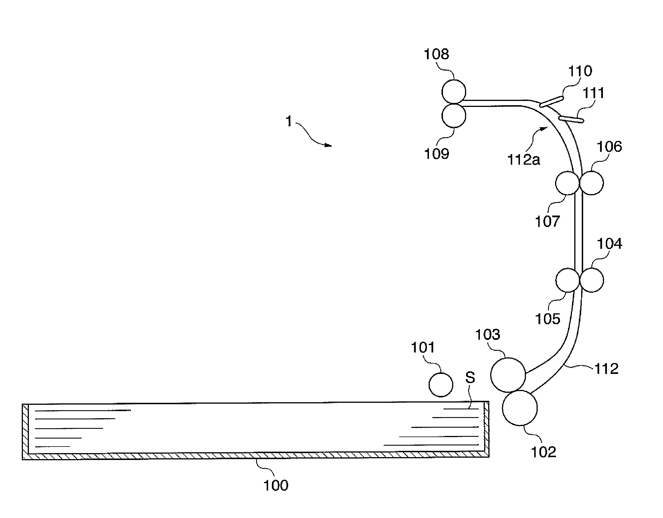
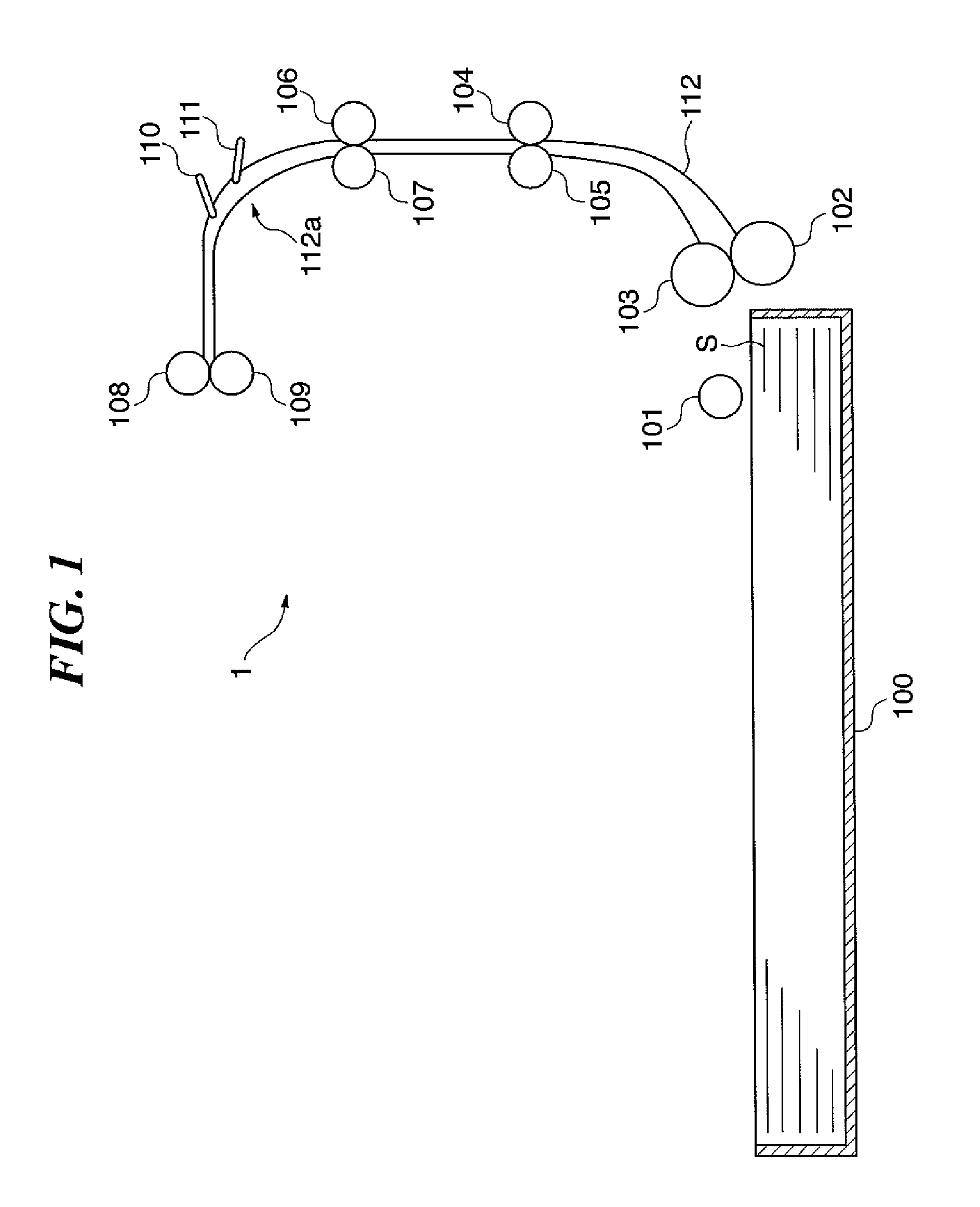
[0037]FIG. 1 is a configuration diagram of a conveying path of an image forming apparatus according to a first embodiment.

[0038]In FIG. 1, an image forming apparatus 1 feeds transfer paper S set in a paper feed cassette 100 to an image forming unit (not shown, see FIGS. 5 and 6) through a conveying path 112, and forms an image through steps of such as transferring and fixing the image onto the transfer paper. In an embodiment, the image forming apparatus 1 is configured as a multi function peripheral having a plurality of functions (a copy function, a printer function, a FAX function, a scanner function and a network function).

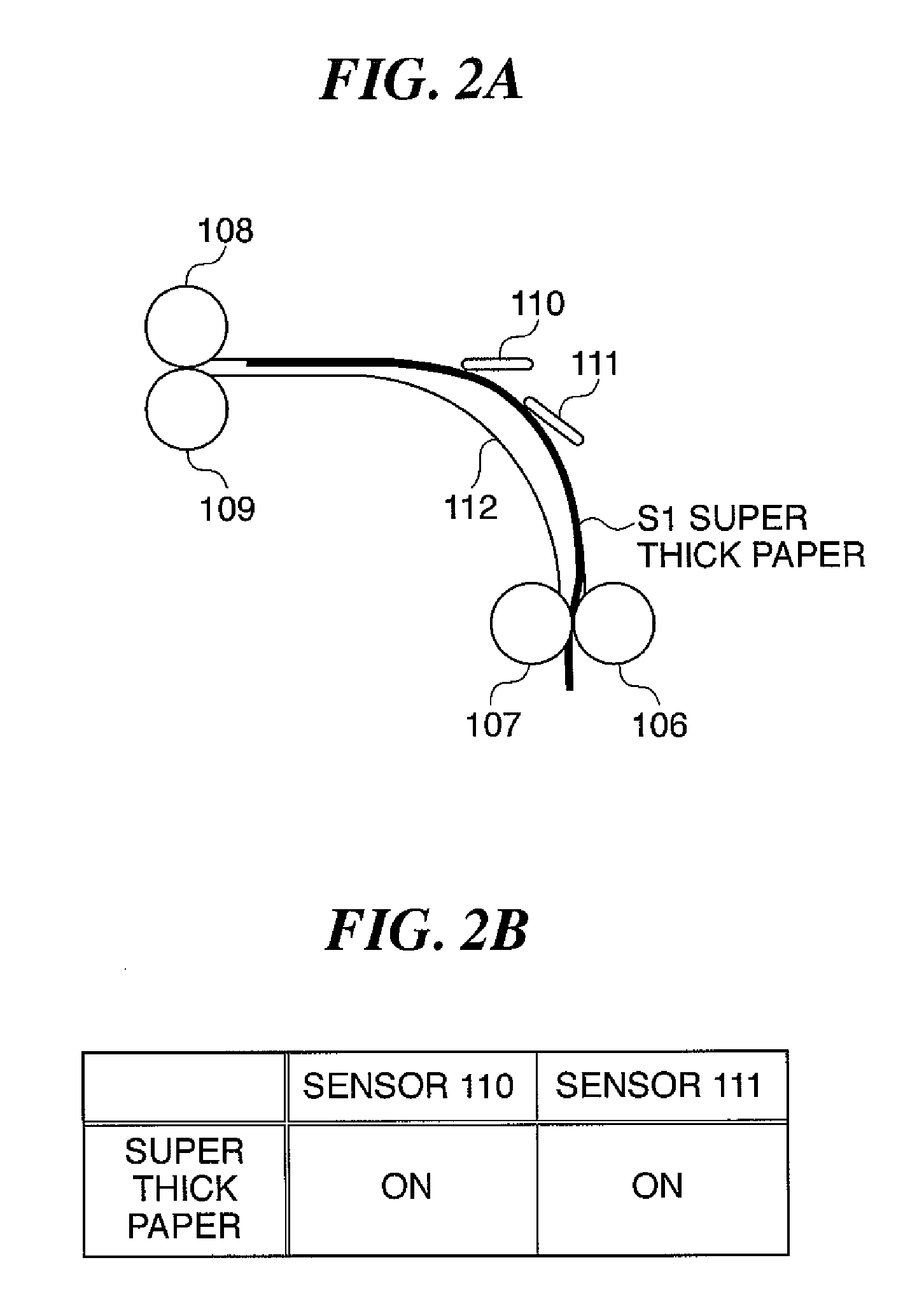
[0039]Between the paper feed cassette 100 and the conveying path 112, paper feed rollers 101 through 103 are disposed. Along the conveying path 112, conveying rollers 104 through 109 are disposed. Further, around a bent part 112a of the conveying path 112, the transfer paper detecting sensors 110 and 111 are disposed. The transfer paper detecting sensors 110 a...

second embodiment

[0063]A second embodiment of the present invention differs from the above described first embodiment in performance of image forming control based on detection of transfer paper shown in a flowchart in FIG. 10. Other elements in this embodiment will not be further described since they are same as those corresponding to the above described first embodiment (FIGS. 1, 5 and 6).

[0064]FIG. 8 is a configuration diagram showing connections among image forming apparatuses according to this embodiment of the present invention, a network server and other information instruments.

[0065]In FIG. 8, a plurality of image forming apparatuses (multi function peripherals) 150, 151 and 152, a plurality of clients (PC) 154, 155 and 156, and the network server (data server) 129 are connected to one another via a network 157. The network 157 can be wired or wireless. Each of the above apparatuses effectively utilizes information of the other apparatuses via the network 157. The network server 129 monitors...


PUM


Abstract

In an image forming apparatus, a type of paper conveyed through a conveying path is determined based on combination of sensing signals obtained from a plurality of sensing units. Each of the sensing units is movable between an actuating position and a retracting position as a paper is conveyed through a conveying path. Based on the type of paper determined based on combination of sensing signals obtained from the plurality of sensing units, a control unit of the image forming apparatus controls an image forming unit forming an image on the conveyed paper.

Description

BACKGROUND OF THE INVENTION[0001]1. Field of the Invention[0002]The present invention relates to an image forming apparatus (e.g., copying machine, printer, facsimile) having a function to sense a kind of paper conveyed through its conveying path, and a control method therefor, and program.[0003]2. Description of the Related Art[0004]Conventionally, an image forming apparatus such as a copying machine, a printer or a facsimile forms an image by transferring an image to a transfer paper based on image data read from an original or image data supplied from other information processing apparatuses. An image forming apparatus may use various types of transfer papers, including thick papers and plain papers. Each type of transfer paper may require different control condition for forming an image by the image forming apparatus.[0005]In a conventional image forming apparatus, a control unit conducts optimal control depending on the type of transfer paper set by a user using an operation un...

Claims


Application Information

Patent Timeline
Patent Type & Authority Patents(United States)
IPC IPC(8): G03G15/00
CPCG03G15/5029G03G2215/00738
Inventor WATANABE, KAZUHITO
Owner CANON KK
Why Eureka
Try Eureka