Vertebral replacement and distraction device for placing said implant

Inactive Publication Date: 2010-10-26
SCIENTX
View PDF42 Cites 35 Cited by
  • Summary
  • Abstract
  • Description
  • Claims
  • Application Information

AI Technical Summary

Benefits of technology

[0007]The object of the invention is to overcome these prior art shortcomings by proposing a vertebral replacement implant designed to allow it

Problems solved by technology

Said implant therefore has irreversible locking preventing any possible withdrawal which is a major drawback under certain inserting conditions.
The main dis

Method used


Image

  • Vertebral replacement and distraction device for placing said implant
  • Vertebral replacement and distraction device for placing said implant
  • Vertebral replacement and distraction device for placing said implant

Examples


Embodiment Construction

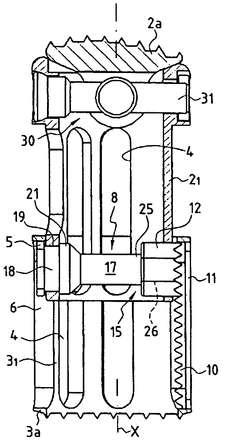
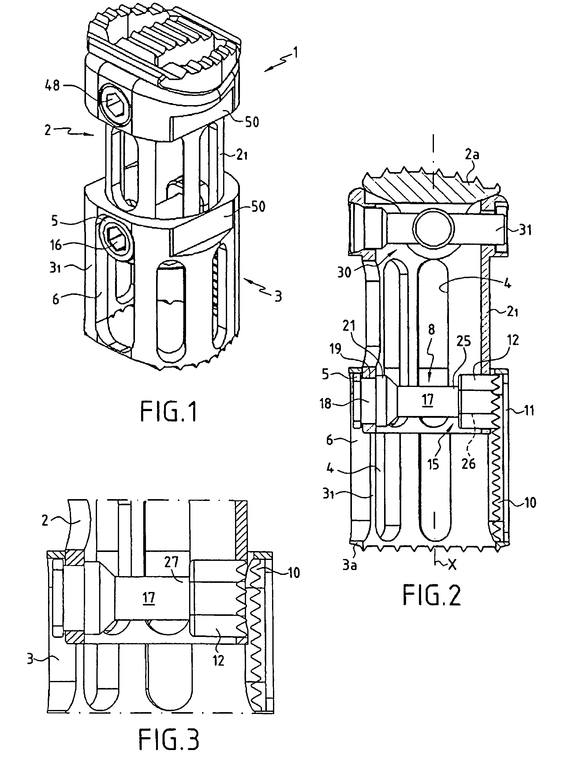
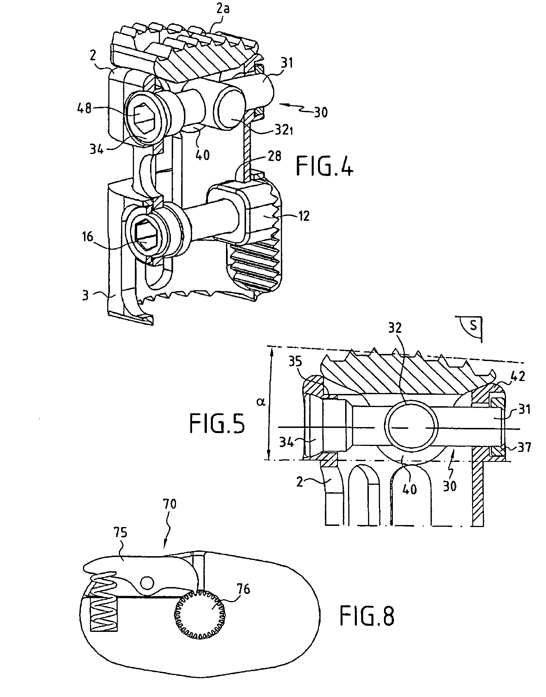
[0043]As shown more precisely FIGS. 1 to 4, the subject of the invention concerns a vertebral replacement implant 1 comprising a first so-called male hollow longitudinal element 2 and a second so-called female hollow longitudinal element 3. Each element 2, 3 respectively comprises a body 21, 31 of general tubular shape extending along a longitudinal axis X. The male body 21 is adapted to engage partly inside the female body 31 so that they extend co-axially in relation to one another. The male body 21 has an outer casing of substantially identical shape and section, allowing clearance, to the inner bore delimited by the female body 31. Preferably, the male 21 and female 31 bodies comprise recesses 4 for passing bone anchor volume.

[0044]According to one characteristic of the invention, the male 2 and female 3 elements are slidably mounted with respect to each other along their common longitudinal axis X. In the illustrated example, the sliding assembly between the male 2 and female 3...


PUM


Abstract

A vertebral replacement implant includes two longitudinal elements slidably mounted with respect to each other, and locking elements. These locking elements include, on one of the longitudinal elements, an anchor surface, and on the other of the longitudinal elements, an anchor shoe guided in translation to take up a first position in which the elements slide freely with respect to each other, and a second position in which the anchor shoe cooperates with the anchor surface to lock the elements together, with a system converting a rotational movement into a translational movement transmitted to the anchor shoe.

Description

[0001]This application is a filing under 35 USC 371 of PCT / FR2004 / 000262 filed Feb. 5, 2004.BACKGROUND OF THE INVENTION[0002]The present invention pertains to a medical implant intended to replace a vertebra, at least in part, with a view to maintaining the normal spacing between the adjacent vertebrae.[0003]The subject of the invention finds application for vertebral replacement in the cervical, thoracic or lumbar region.[0004]In the prior art, various variants are known for fabricating a replacement implant also called a corporectomy implant. Patent application FR 2 730 158 for example describes a spacer implant comprising two telescoping hollow elements having complementary shapes on their mutually opposite faces which engage to allow distraction movement of the elements while preventing their compression movement.[0005]Said spacer implant makes it possible to adjust the length of the implant in situ while ensuring relative distancing between the two elements by sliding the eleme...

Claims


Application Information

Patent Timeline
IPC IPC(8): A61F2/44A61F2/00A61F2/02A61F2/30A61F2/46
CPCA61F2/44A61F2/4611A61F2/4637A61F2/4455A61F2002/30131A61F2002/3024A61F2002/30484A61F2002/30489A61F2002/30512A61F2002/3052A61F2002/30522A61F2002/30525A61F2002/30538A61F2002/3055A61F2002/30551A61F2002/30601A61F2002/30777A61F2002/30787A61F2002/30789A61F2002/30841A61F2002/30904A61F2002/4475A61F2002/4622A61F2002/4624A61F2002/4627A61F2002/4628A61F2002/4635A61F2002/4638A61F2220/0025A61F2230/0013A61F2230/0069A61F2250/0006A61F2002/30235A61F2002/30487A61F2002/30507A61F2/4603A61F2002/30593
Inventor ASSAKER, RICHARD
Owner SCIENTX
Why Eureka
Try Eureka