Vectored thruster augmented aircraft

a thruster and augmented technology, applied in the field can solve the problems of limited forward limited control options of conventional helicopter pilots, and difficulty in adjusting the speed of rotary wing aircraft, so as to improve the speed, range and fuel economy, and increase the speed of yaw control.

Active Publication Date: 2010-11-02
PIASECKI AIRCRAFT CORP
View PDF4 Cites 20 Cited by
  • Summary
  • Abstract
  • Description
  • Claims
  • Application Information

AI Technical Summary

Benefits of technology

[0016]When the two thrusters are in the first position, the axes of rotation of the thruster propellers are generally parallel to the longitudinal axis of the rotary wing aircraft and the exhaust of the two vectored thrusters is directed to the rear of the aircraft. In this configuration, the vectored thrusters provide forward thrust during forward acceleration and during coordinated flight. The forward thrust of the vectored thrusters allows the helicopter to realize the benefits of greater acceleration, speed, range, and fuel economy compared to a helicopter without vectored thrusters. In this configuration, the differentially controllable pitch of the propellers provides increased yaw control by selectably applying yaw moments to the aircraft. The differentially controllable horizontal vanes provide increased roll control by selectably applying roll moments to the aircraft.
[0018]The tilt of the vectored thrusters may be selected to be intermediate between the horizontal and vertical directions. An intermediate tilt may be selected, for example, during forward acceleration to maintain air flow through the vectored thrusters and maximize lift generated by the vectored thrusters.
[0021]Each of the two vectored thrusters is equipped with vanes mounted in the stream of air exiting the vectored thruster. The vanes selectably (and differentially) redirect the exhaust of the two vectored thrusters, providing control flexibility to the control system and the pilot. For example, when the axis of rotation of the thruster propellers is oriented in the generally vertical direction, the pilot or control system may direct the vanes to channel the exhaust of the vectored thrusters toward the front or to the rear of the aircraft. If the vanes of both vectored thrusters are directed forward, the reaction forces generated by the exhaust air acting on the vanes urge the helicopter in the aft direction. If the vanes of both vectored thrusters are directed aft, the reaction forces urge the helicopter forward. If the vanes of one of the vectored thrusters are directed forward and the vanes of the other thruster are directed aft, the vectored thrusters apply a yawing moment to the helicopter. If the vanes of both vectored thrusters are in the central position, the vectored thrusters provide only lift. The use of vanes provides options for the control of directional movement and yaw when the helicopter is in hover or moving at a low speed.
[0024]The control system may be configured so that the operation of the vectored thrusters and associated controls is automatic and does not require separate attention from the pilot. If the control system is so configured, the pilot operates the helicopter using conventional flight controls. The control system receives the conventional throttle, collective, cyclic and yaw control inputs from the pilot and applies pre-determined control rules to coordinate the simultaneous operation of the vectored thruster tilt, differential propeller pitch and differential vane angle. The control system will apply the control rules to vary smoothly and continuously the vectored thruster tilt, vane angle and propeller pitch throughout the range of vectored thruster tilt positions to achieve the desired lift, thrust, yawing moment and rolling moment appropriate to the flight condition and pilot command.

Problems solved by technology

The forward speed of a rotary wing aircraft is limited by advancing blade compression effects and retreating blade stall.
The use of a thruster can complicate the operation of the rotary wing aircraft in hover.
The pilot of the conventional helicopter therefore has few control options.

Method used


Image

  • Vectored thruster augmented aircraft
  • Vectored thruster augmented aircraft
  • Vectored thruster augmented aircraft

Examples


Embodiment Construction

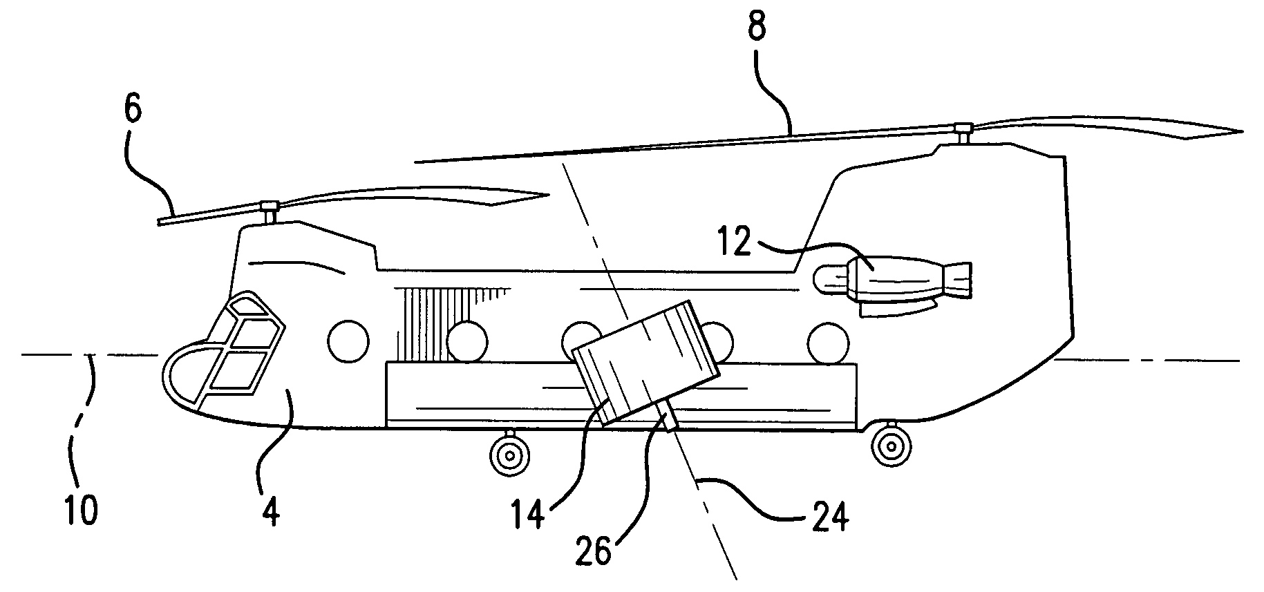
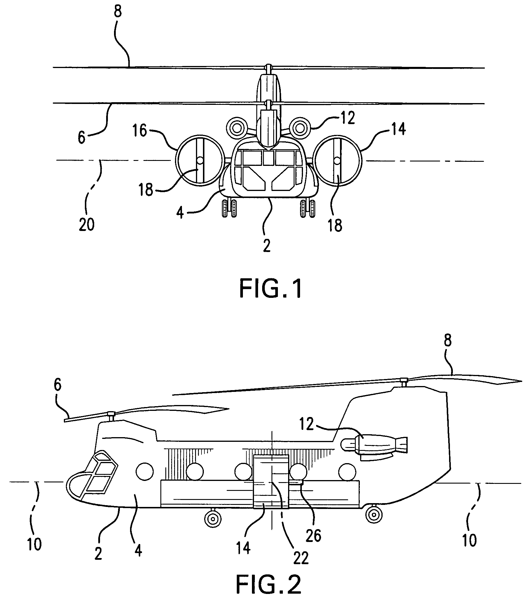
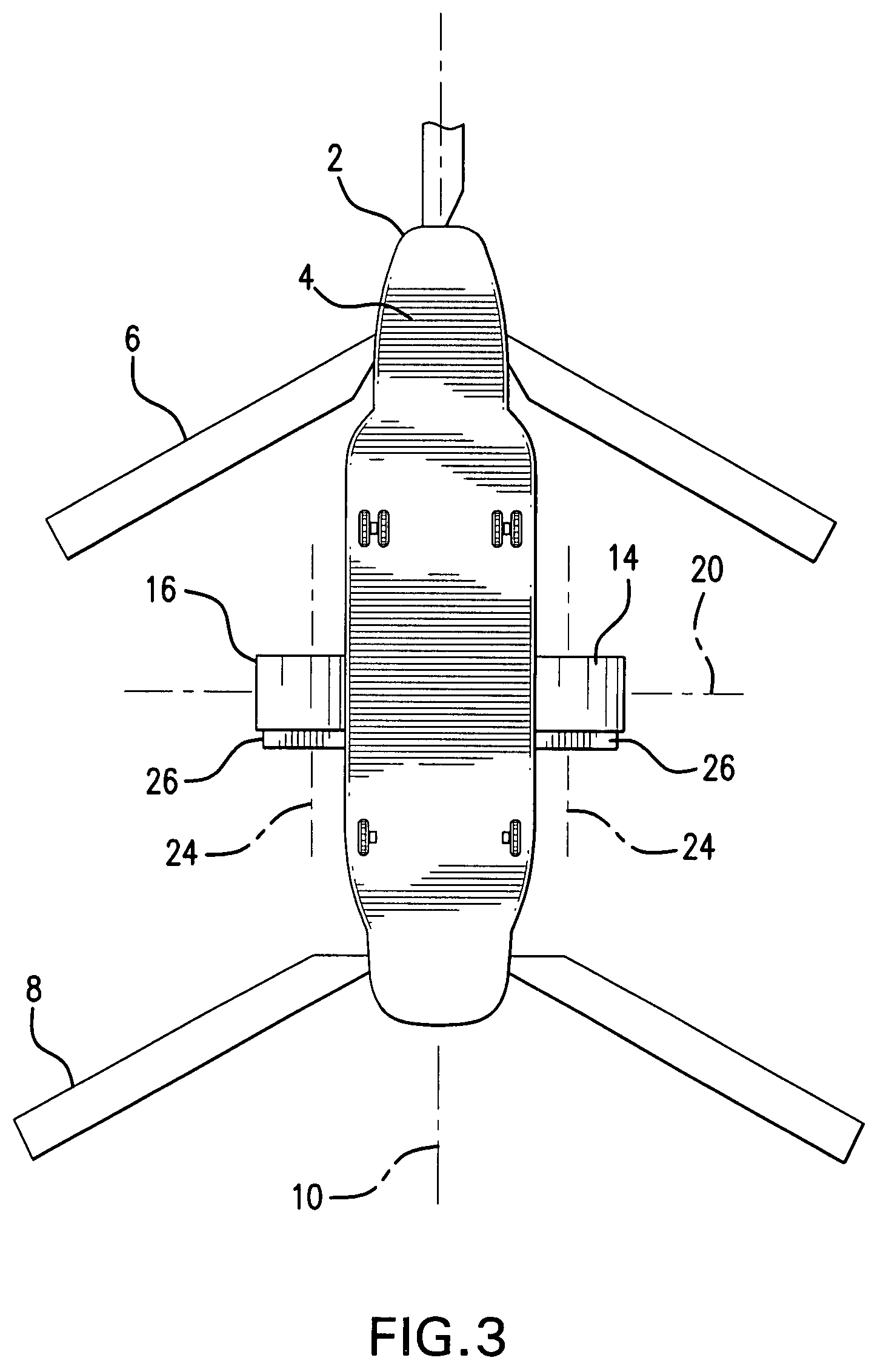
[0050]A tandem-rotor helicopter equipped with the Invention is illustrated by FIGS. 1 through 8 and 13 through 16. As illustrated by FIGS. 1 and 2, a tandem-rotor helicopter 2, such as a Boeing CH-47 Chinook, has a fuselage 4, a fore main rotor 6 and an aft main rotor 8. The helicopter 2 has a longitudinal axis 10 corresponding to a direction of forward travel of the helicopter 2. One or more engines 12 provide power to operate the fore and aft main rotors 6, 8 and the other systems of the helicopter 2.

[0051]The helicopter 2 is equipped with a port vectored thruster 14 and a starboard vectored thruster 16 located on opposing sides of fuselage 4. The vectored thrusters 14, 16 are ducted fans each having a controllable-pitch propeller 18. Vectored thrusters 14, 16 may be selectably tilted about a transverse axis 20 between a first position, illustrated by FIGS. 1-3, and a second position, illustrated by FIGS. 4-6. First and second positions of vectored thrusters 14, 16 differ by a til...


PUM


Abstract

The Invention is a rotary-wing aircraft having at least two vectored thrusters that may be tilted from a horizontal to a vertical position and to positions intermediate between the horizontal and vertical positions. The two vectored thrusters are equipped with propellers having separately variable pitch. The two vectored thrusters also are equipped with vanes having selectable vane angles to direct separately the air flow from the two vectored thrusters. A control system detects the flight condition of the aircraft and selects vectored thruster control settings corresponding to the detected flight condition and consistent with predetermined control rules to provide lift, thrust, yaw moments and roll moments.

Description

CROSS REFERENCE TO RELATED APPLICATION[0001]This is a continuation-in-part application based upon U.S. Patent Application entitled Vectored Thruster Augmented Aircraft, application Ser. No. 11 / 776,385, filed on Jul. 11, 2007.I. BACKGROUND OF THE INVENTION[0002]A. Field of the Invention[0003]The Invention is a rotary wing aircraft featuring two or more laterally spaced-apart vectored thrusters that may be tilted between a first and a second position. The vectored thrusters may be equipped with adjustable horizontal vanes to direct selectably the flow of air from the vectored thrusters. The vectored thrusters also may be equipped with controllable-pitch propellers to selectably control the amount of thrust generated by each vectored thruster. The vectored thrusters, vanes and controllable-pitch propellers can be configured selectably to provide additional lift and to allow the rotary wing aircraft to reach higher ultimate speeds. The vectored thrusters, vanes and controllable pitch pr...

Claims


Application Information

Patent Timeline
Patent Type & Authority Patents(United States)
IPC IPC(8): B64C27/82B64C27/08B64C27/52
CPCB64C27/28
Inventor PIASECKI, FREDERICK W.PIASECKI, FRANK N.
Owner PIASECKI AIRCRAFT CORP
Why Eureka
Try Eureka