Coaxial cable continuity connector

a continuity connector and coaxial cable technology, applied in the direction of coupling devices, two-pole connections, coupling devices, etc., can solve the problems of loss of ground, discontinuity, and connectors that are not properly tightened or otherwise installed to the interface por

Active Publication Date: 2010-11-02
PPC BROADBAND INC
View PDF129 Cites 156 Cited by
  • Summary
  • Abstract
  • Description
  • Claims
  • Application Information

AI Technical Summary

Benefits of technology

[0004]A first aspect of the present invention provides a coaxial cable continuity connector comprising; a connector body; a post engageable with connector body, wherein the post includes a flange having a tapered surface; a nut, wherein the nut includes an internal lip having a tapered surface, wherein the tapered surface of the nut oppositely corresponds to the tapered surface of the post when the nut and post are operably axially located with respect to each other when the coaxial cable continuity connector is assembled; and a continuity member disposed between and contacting the tapered surface of the post and the tapered surface of the nut, so that the continuity member endures a moment resulting from the contact forces of the opposite tapered surfaces, when the continuity connector is assembled.

Problems solved by technology

However, often connectors are not properly tightened or otherwise installed to the interface port and proper electrical mating of the connector with the interface port does not occur.
Moreover, structure of common connectors may permit loss of ground and discontinuity of the electromagnetic shielding that is intended to be extended from the cable, through the connector, and to the corresponding coaxial cable interface port.

Method used


Image

  • Coaxial cable continuity connector
  • Coaxial cable continuity connector
  • Coaxial cable continuity connector

Examples


Embodiment Construction

[0018]Although certain embodiments of the present invention are shown and described in detail, it should be understood that various changes and modifications may be made without departing from the scope of the appended claims. The scope of the present invention will in no way be limited to the number of constituting components, the materials thereof, the shapes thereof, the relative arrangement thereof, etc., and are disclosed simply as an example of embodiments of the present invention.

[0019]As a preface to the detailed description, it should be noted that, as used in this specification and the appended claims, the singular forms “a”, “an” and “the” include plural referents, unless the context clearly dictates otherwise.

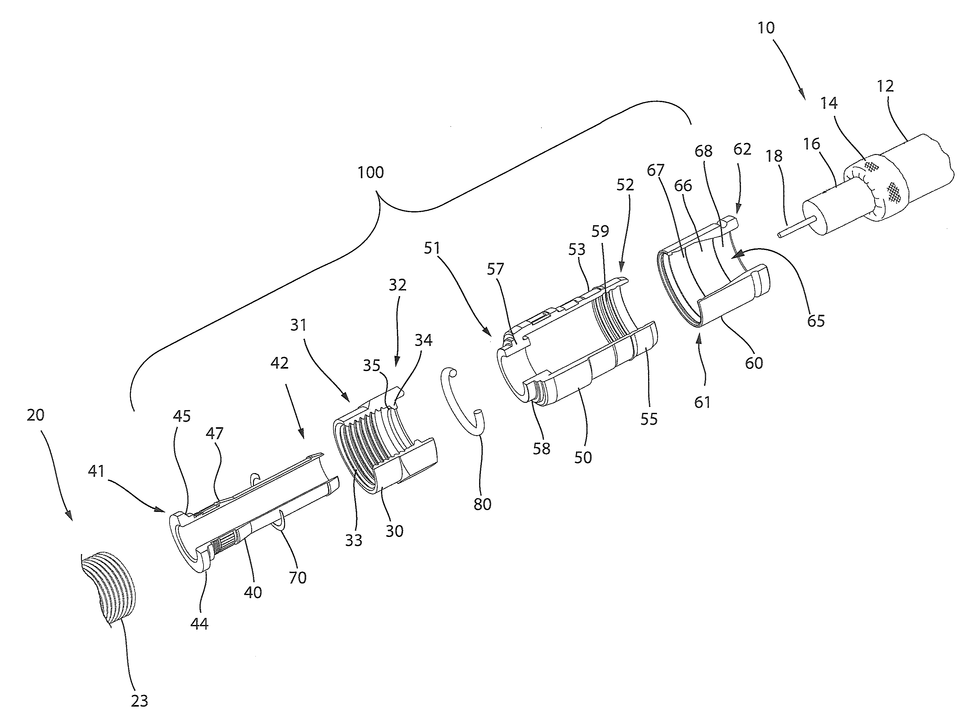
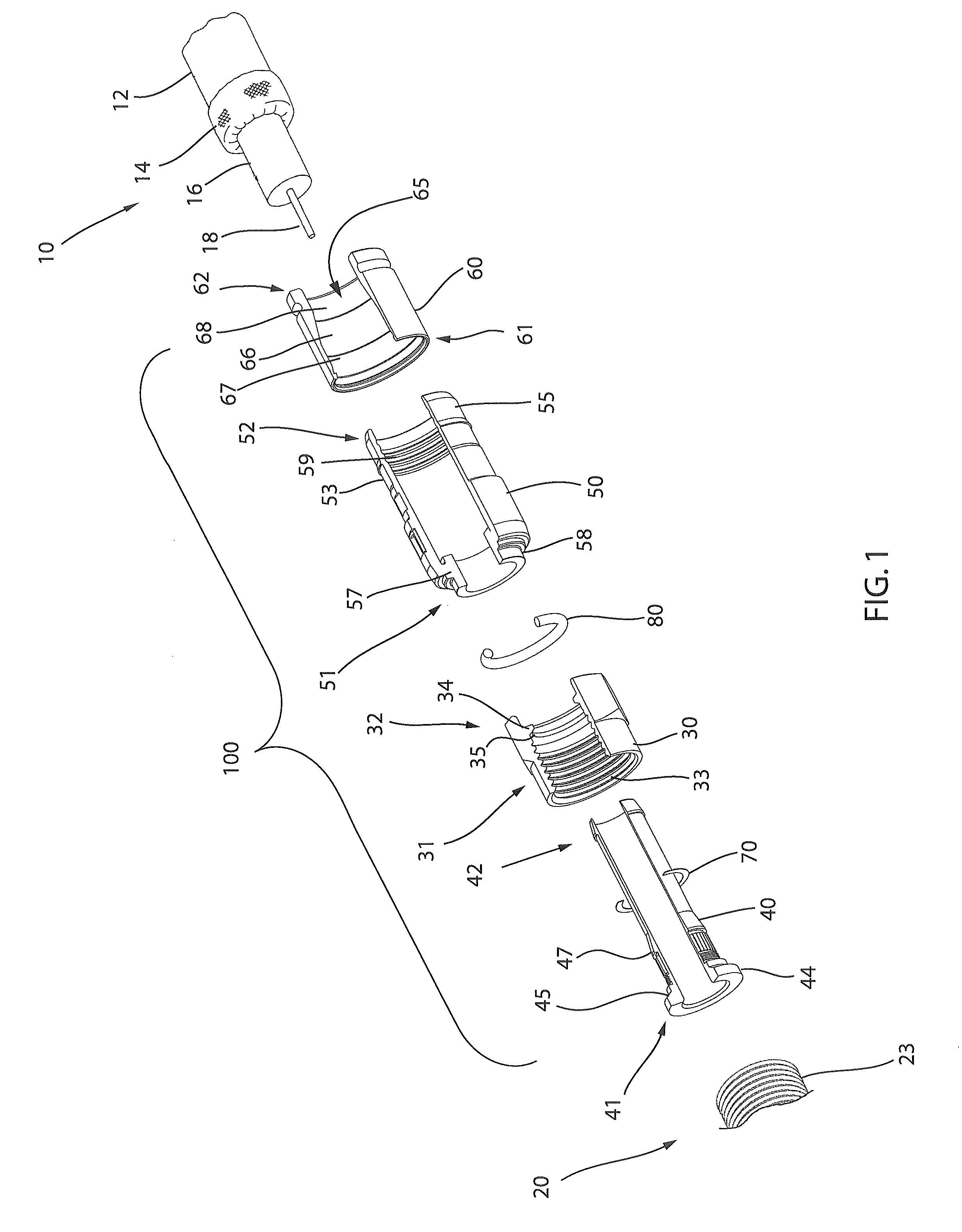
[0020]Referring to the drawings, FIG. 1 depicts one embodiment of a continuity connector 100. The continuity connector 100 may be operably affixed to a coaxial cable 10 having a protective outer jacket 12, a conductive grounding shield 14, an interior dielectric 16 ...


PUM

PropertyMeasurementUnit
contact forcesaaaaaaaaaa
electricalaaaaaaaaaa
electricallyaaaaaaaaaa

Abstract

A coaxial cable continuity connector comprising a connector body, a post engageable with connector body, wherein the post includes a flange having a tapered surface, a nut, wherein the nut includes an internal lip having a tapered surface, wherein the tapered surface of the nut oppositely corresponds to the tapered surface of the post when the nut and post are operably axially located with respect to each other when the coaxial cable continuity connector is assembled, and a continuity member disposed between and contacting the tapered surface of the post and the tapered surface of the nut, so that the continuity member endures a moment resulting from the contact forces of the opposite tapered surfaces, when the continuity connector is assembled, is provided.

Description

CROSS-REFERENCE TO RELATED APPLICATIONS[0001]This application claims the priority benefit of U.S. Provisional Patent Application No. 61 / 166,247 filed Apr. 2, 2009, and entitled COAXIAL CABLE CONTINUITY CONNECTOR.FIELD OF THE INVENTION[0002]The present invention relates to F-type connectors used in coaxial cable communication applications, and more specifically to connector structure extending continuity of an electromagnetic interference shield from the cable and through the connector.BACKGROUND OF THE INVENTION[0003]Broadband communications have become an increasingly prevalent form of electromagnetic information exchange and coaxial cables are common conduits for transmission of broadband communications. Coaxial cables are typically designed so that an electromagnetic field carrying communications signals exists only in the space between inner and outer coaxial conductors of the cables. This allows coaxial cable runs to be installed next to metal objects without the power losses t...

Claims


Application Information

Patent Timeline
Patent Type & Authority Patents(United States)
IPC IPC(8): H01R9/05
CPCH01R24/40H01R9/0524H01R13/622Y10T29/49195H01R2103/00
Inventor PURDY, ERIC
Owner PPC BROADBAND INC
Why Eureka
Try Eureka