Tire pressure monitoring system

a technology of monitoring system and tire pressure, which is applied in the direction of phase-modulated carrier system, instruments, anti-theft devices, etc., can solve the problems of increasing the area of the board and increasing the cost, and achieve the effect of reducing the variation in the rate of data transmission and high frequency stability

Active Publication Date: 2010-11-02
HITACHI ASTEMO LTD
View PDF11 Cites 5 Cited by
  • Summary
  • Abstract
  • Description
  • Claims
  • Application Information

AI Technical Summary

Benefits of technology

[0009]In a method described in JP-A-2003-94917, accuracy of the rate of transmission of data via wireless communications is ensured by a program executed by a microcomputer, which is operated by a drive clock signal generated by a quartz oscillator having high frequency stability.
[0010]The increase in the number of oscillators leads to an increase in the area of a board and an increase in the cost.
[0011]It is, therefore, an object of the present invention to provide a tire pressure monitoring system capable of ensuring accuracy of the rate of transmission of data via wireless communications without an increase in the number of oscillators and an increase in the cost.
[0014]The tire pressure monitoring system according to the present invention is capable of reducing variations in rates of data transmissions performed by devices via wireless communications by means of a simple circuit of each device without using an oscillator having high frequency stability for generation of a drive clock signal for operating a microcomputer.

Problems solved by technology

The increase in the number of oscillators leads to an increase in the area of a board and an increase in the cost.

Method used


Image

  • Tire pressure monitoring system
  • Tire pressure monitoring system
  • Tire pressure monitoring system

Examples


first embodiment

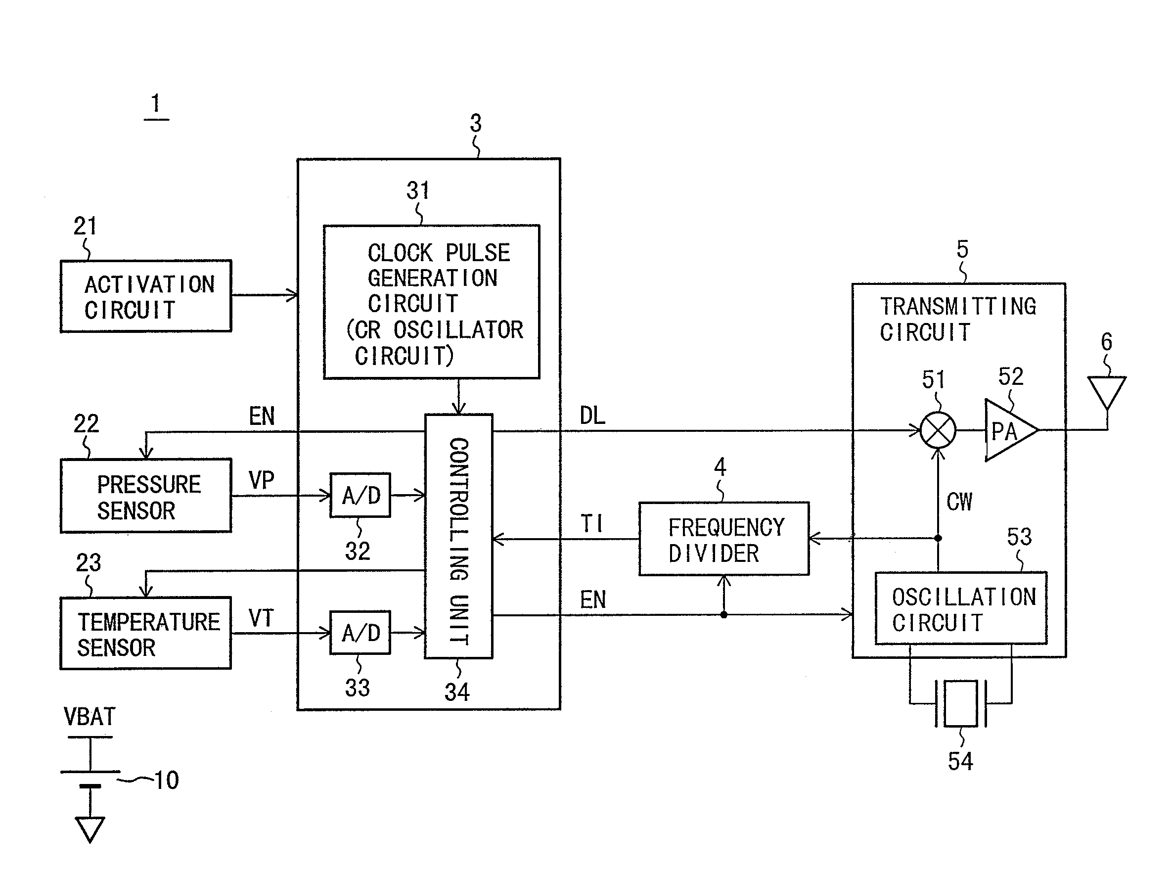
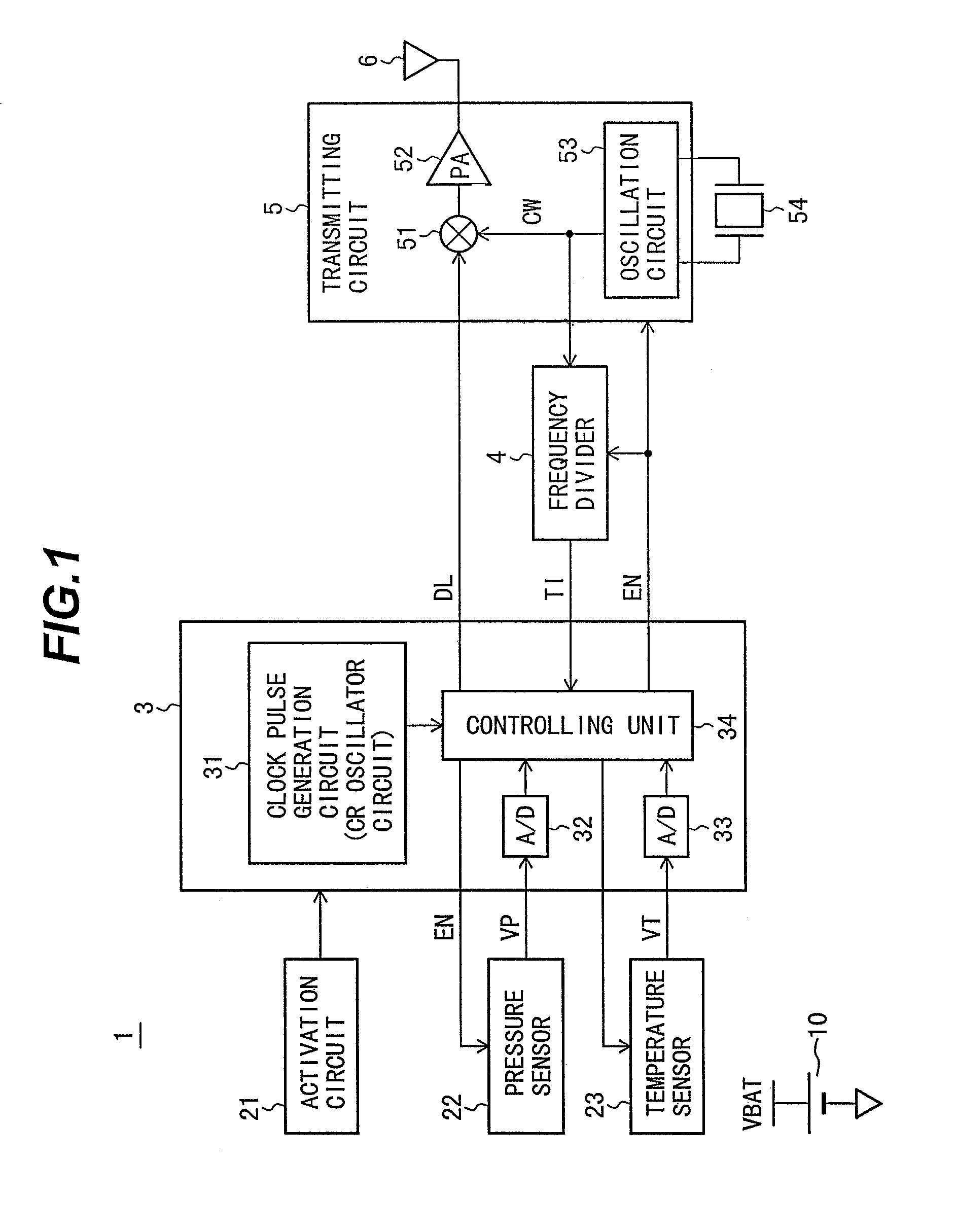
[0028]A description will be made of the configuration and operations of a tire pressure monitoring system according to a first embodiment of the present invention with reference to FIG. 1 to FIG. 7.

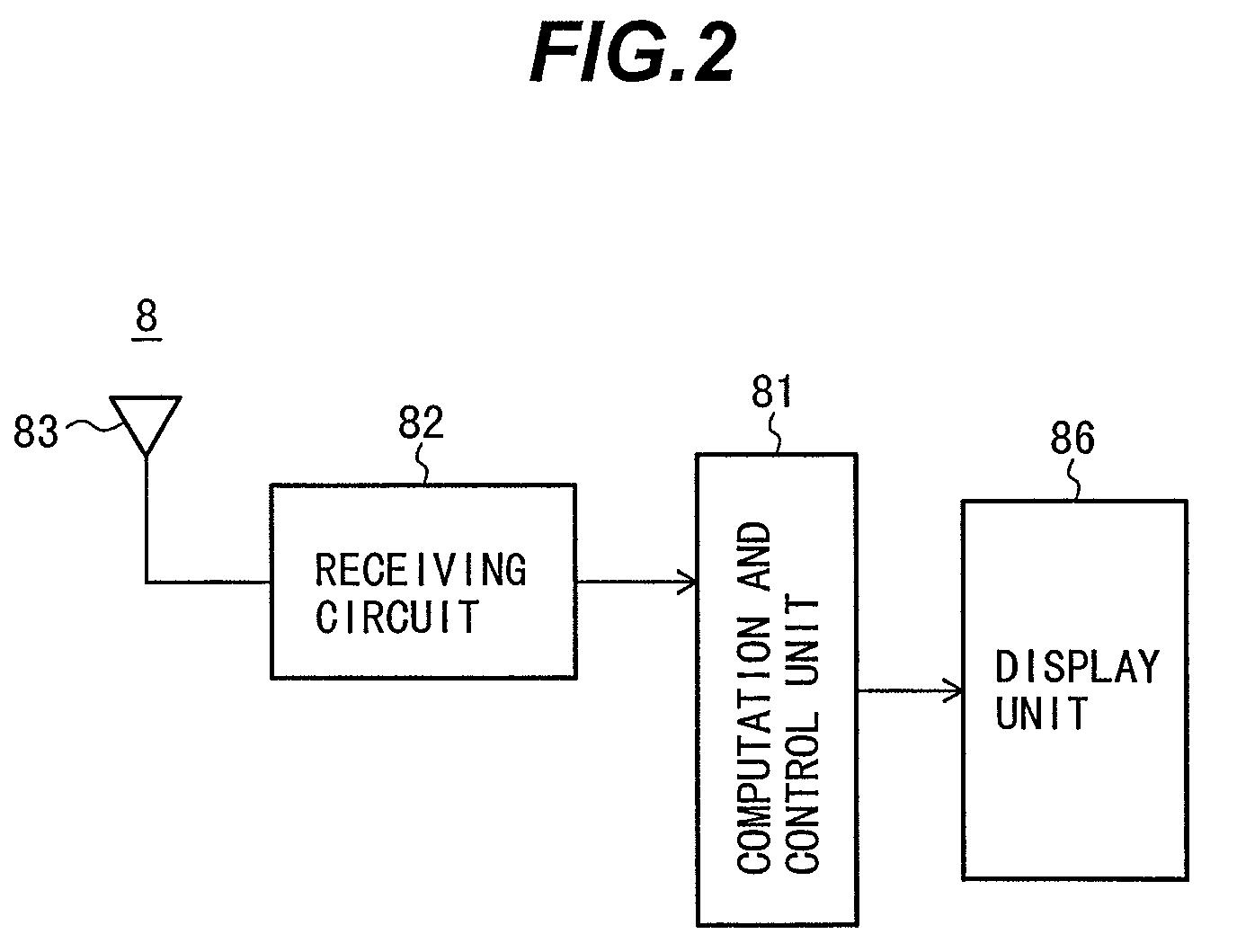
[0029]First, a description will be made of the entire construction of the system using the tire pressure monitoring apparatus according to the first embodiment of the present invention with reference to FIG. 1 to FIG. 4. FIG. 1 is a diagram showing an outline configuration of a tire pressure measuring module 1. FIG. 2 is a block diagram showing an outline configuration of an in-vehicle device 8. FIG. 3 is a diagram showing the entire configuration of the tire pressure monitoring system when viewed from a bottom surface of a vehicle.

[0030]The entire configuration of the tire pressure monitoring system will be described with reference to FIG. 3. Referring to FIG. 3, a vehicle 7 has tires 71a to 71d arranged on the front-left, front-right, rear-left, and rear-right sides thereof, respectivel...

second embodiment

[0066]A description will be made of the configuration and operations of a tire pressure monitoring system according to a second embodiment of the present invention with reference to FIG. 8. Since the basic configuration of the tire pressure monitoring system according to the second embodiment is similar to that of the tire pressure monitoring system according to the first embodiment, only different points between the first and second embodiments will be described.

[0067]That is, a frequency multiplier 55 is provided between the oscillator circuit 53 and the multiplier 51 in the second embodiment as shown in FIG. 8. In addition, the oscillator 54 provided for the transmitting circuit 5 is, for example, a crystal oscillator having an oscillation frequency of 9.84375 MHz in the second embodiment in place of the surface acoustic wave oscillator according to the first embodiment. The frequency multiplier 55 multiplies the oscillation frequency by 32 to obtain a signal having a frequency o...

third embodiment

[0070]A description will be made of the configuration and operations of a tire pressure monitoring system according to a third embodiment of the present invention with reference to FIG. 9. Since the basic configuration of the tire pressure monitoring system according to the third embodiment is similar to that of the tire pressure monitoring system according to the first embodiment, only different points between the first and third embodiments will be described.

[0071]That is, frequency shift keying (FSK) modulation is used in a transmitting circuit 50 in the third embodiment in place of the amplitude shift keying modulation used in the first embodiment, as shown in FIG. 9. Specifically, the frequency of a carrier wave oscillated by an oscillator circuit 56 is switched to a frequency of, for example, 315.0 MHz or 315.1 MHz by means of a signal output to the data signal line DL and indicating “0” or “1”.

[0072]In this case, the frequency of a timing signal generated by the frequency div...


PUM

PropertyMeasurementUnit
pressureaaaaaaaaaa
frequenciesaaaaaaaaaa
frequencyaaaaaaaaaa

Abstract

A tire pressure monitoring system is capable of ensuring accuracy of the rate of transmission of data via wireless communications without an increase in the number of oscillators and an increase in the cost. The tire pressure monitoring system includes a tire pressure measuring module. The tire pressure measuring module has a microcomputer, an activation control circuit, a pressure sensor, a temperature sensor, a frequency divider, a transmitting circuit, and a battery. The microcomputer has a clock pulse generator, analog-to-digital converter circuits and a controller. The transmitting circuit has an oscillator circuit. The frequency divider divides the frequency of a carrier wave CW output from the oscillator circuit to generate a clock signal, and outputs the clock signal to the controller included in the microcomputer. The clock signal is used for the timing for outputting data to a data signal line DL. The clock signal for high precision data transmission can be generated without the need to provide an expensive oscillator in the microcomputer since the oscillator circuit is used in the transmitting circuit, and the clock signal used for data transmission by the microcomputer is generated by the inexpensive frequency divider.

Description

BACKGROUND OF THE INVENTION[0001]1. Field of the Invention[0002]The present invention relates to a system for monitoring pressure of a gas present in a tire used for a vehicle or the like.[0003]2. Description of the Related Art[0004]In recent years, there has been increasing attention to a system for measuring pressure of a gas present in a tire used for a vehicle or the like and providing an alarm when the pressure is reduced. This results from the following: it is necessary that the pressure of a gas present in a tire used for a vehicle be maintained to approximately 220 kPa at a room temperature; and a reduction in the pressure of the gas present in the tire may not only degrade ride comfort or fuel efficiency but also break the tire.[0005]In the United States, it is required that each vehicle have a system for monitoring pressure of gases present in tires used for the vehicle by law.[0006]However, it is difficult that power is supplied from the outside of a tire to a tire pressu...

Claims


Application Information

Patent Timeline
Patent Type & Authority Patents(United States)
IPC IPC(8): B60R25/10B60C23/02B60C23/04B60C23/20G01L17/00G08C17/00G08C17/02
CPCB60C23/0408B60C23/0433B60C23/0462
Inventor MATSUMURA, TAKAFUMI
Owner HITACHI ASTEMO LTD
Why Eureka
Try Eureka