
PLL Apparatus

Active Publication Date: 2009-07-02
NIHON DEMPA KOGYO CO LTD
View PDF4 Cites 2 Cited by
  • Summary
  • Abstract
  • Description
  • Claims
  • Application Information

AI Technical Summary

Benefits of technology

[0006]The present invention was made under such circumstances and has its object to provide a PLL apparatus realizing extremely high frequency stability.
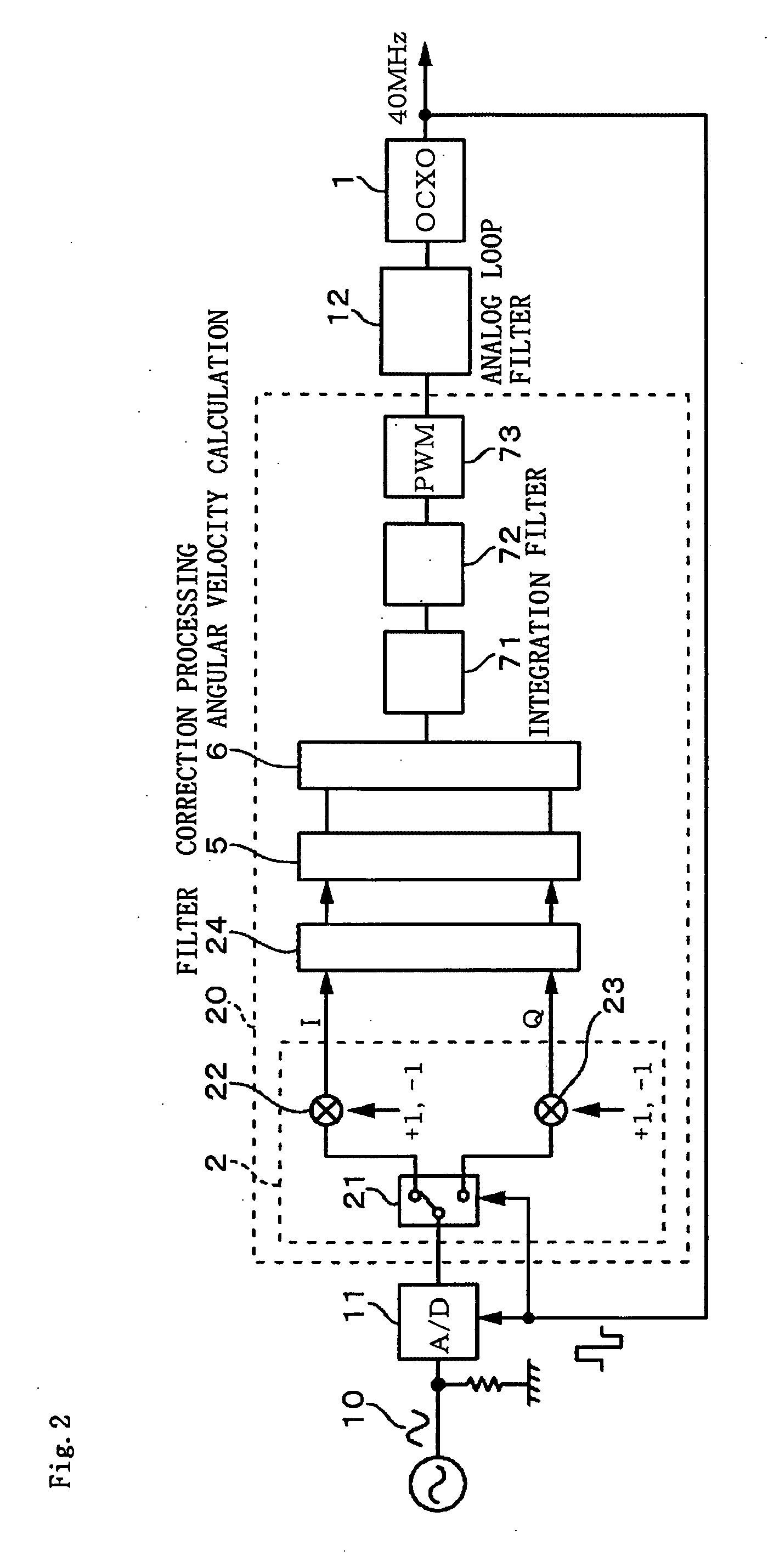
[0015]In the present invention, the external standard signal is sampled based on the frequency signal (oscillation output) from the voltage-controlled oscillation unit, the phase difference therebetween is expressed by the vector, and the oscillation output is controlled according to the angular velocity of the vector. That is, the vector is in a stopped state under the constant phase difference, but if the phase difference changes, the vector rotates, so that the loop operates so as to stop the vector. Therefore, in the present invention, since the phase difference between the frequency signal from the voltage-controlled oscillation unit and the external standard signal is expressed by a digital value, by adjusting the bit numbers thereof, it is possible to make the phase difference constant with high accuracy, and providing that the standard signal has high frequency stability, it is possible to obtain a frequency signal with a desired frequency having extremely high frequency stability (on the condition that the frequency is twice the frequency of the standard signal since the standard signal is sampled). Therefore, the present invention is effective as a reference clock signal generation apparatus such as a frequency synthesizer capable of setting the frequency in a unit of 1 Hz.

Problems solved by technology

A standard signal is obtained from a cesium frequency standard oscillator, a rubidium standard oscillator, and the like, but since the standard signal thereof generally costs high, each of the base stations distributes the standard signal when using it.
For example, the present inventor has been trying to develop a frequency synthesizer having frequency resolution in a 1 Hz unit or lower, but a reference clock signal in such an apparatus needs to have extremely high frequency stability, and a conventional PLL circuit has difficulty in satisfying this requirement.

Method used


Image

  • PLL Apparatus
  • PLL Apparatus
  • PLL Apparatus

Examples


Embodiment Construction

[0030]A PLL circuit of the present invention operates based on a novel principle, and therefore, firstly, an overview of the principle of the operation of the present invention will be briefly described with reference to FIG. 1. In this example, a 40 MHz frequency signal which is, for example, a rectangular wave is obtained based on an external standard signal, for example, a 10 MHz sinusoidal signal which is a standard signal obtained from, for example, a cesium frequency standard oscillator, a rubidium standard oscillator, or the like. This frequency signal may be a sinusoidal signal. The principle of the operation of the present invention is as follows. First, based on a 40 MHz frequency signal which is a rectangular wave output from a voltage-controlled oscillator, for example, an oven-controlled crystal oscillator (OCXO) 1, an A / D (analog / digital) conversion unit 11 samples the standard signal to obtain a digital signal.

[0031]Next, an orthogonal transformation unit 2 applies or...


PUM


Abstract

It is an object of the present invention to provide a PLL apparatus realizing extremely high frequency stability.As a concrete means for solving the problem, an A / D (analog / digital) conversion unit samples a standard signal based on a 40 MHz frequency signal, which is a rectangular wave, from an oven-controlled crystal oscillator (OCXO), and an orthogonal transformation unit applies orthogonal transformation to a digital signal from the A / D conversion unit to extract a real part (I) and an imaginary part (Q) which are complex expression of a phase vector equivalent to a phase difference between the standard signal and the frequency signal from the OCXO. An angular velocity of this vector is detected and a direct-current voltage according to the angular velocity is generated and supplied to the OCXO via a PWM control unit.

Description

TECHNICAL FIELD[0001]The present invention relates to a PLL (Phase Locked Loop) apparatus.BACKGROUND ART[0002]In base stations of mobile communication, terrestrial digital broadcasting, and the like, a frequency reference signal is required to have high frequency stability. A standard signal is obtained from a cesium frequency standard oscillator, a rubidium standard oscillator, and the like, but since the standard signal thereof generally costs high, each of the base stations distributes the standard signal when using it. The distributed standard signal is used, for example, as a reference signal for phase comparison of a PLL circuit, and from this PLL circuit, a reference signal such as, for example, a reference clock signal with a required frequency can be obtained.[0003]As shown in FIG. 14, generally, in a PLL circuit, a phase comparator 104 compares a standard signal 101 and a signal that a frequency divider circuit 103 obtains by frequency-dividing an output signal of a voltag...

Claims


Application Information

Patent Timeline
IPC IPC(8): H03L7/06
CPCH03L7/087H03L7/093H03L7/091
Inventor WAKAMATSU, SHUNICHISHIOBARA, TSUYOSHIONISHI, NAOKI
Owner NIHON DEMPA KOGYO CO LTD
Learn More