

Clock generating device, electronic apparatus, moving object, clock generating method
- Summary
- Abstract
- Description
- Claims
- Application Information
AI Technical Summary
Benefits of technology
Problems solved by technology
Method used
Image

Examples
modification example
4. Modification Example
[0123]The invention is not limited to the present embodiments, and various kinds of modifications are possible without departing from the gist of the invention.
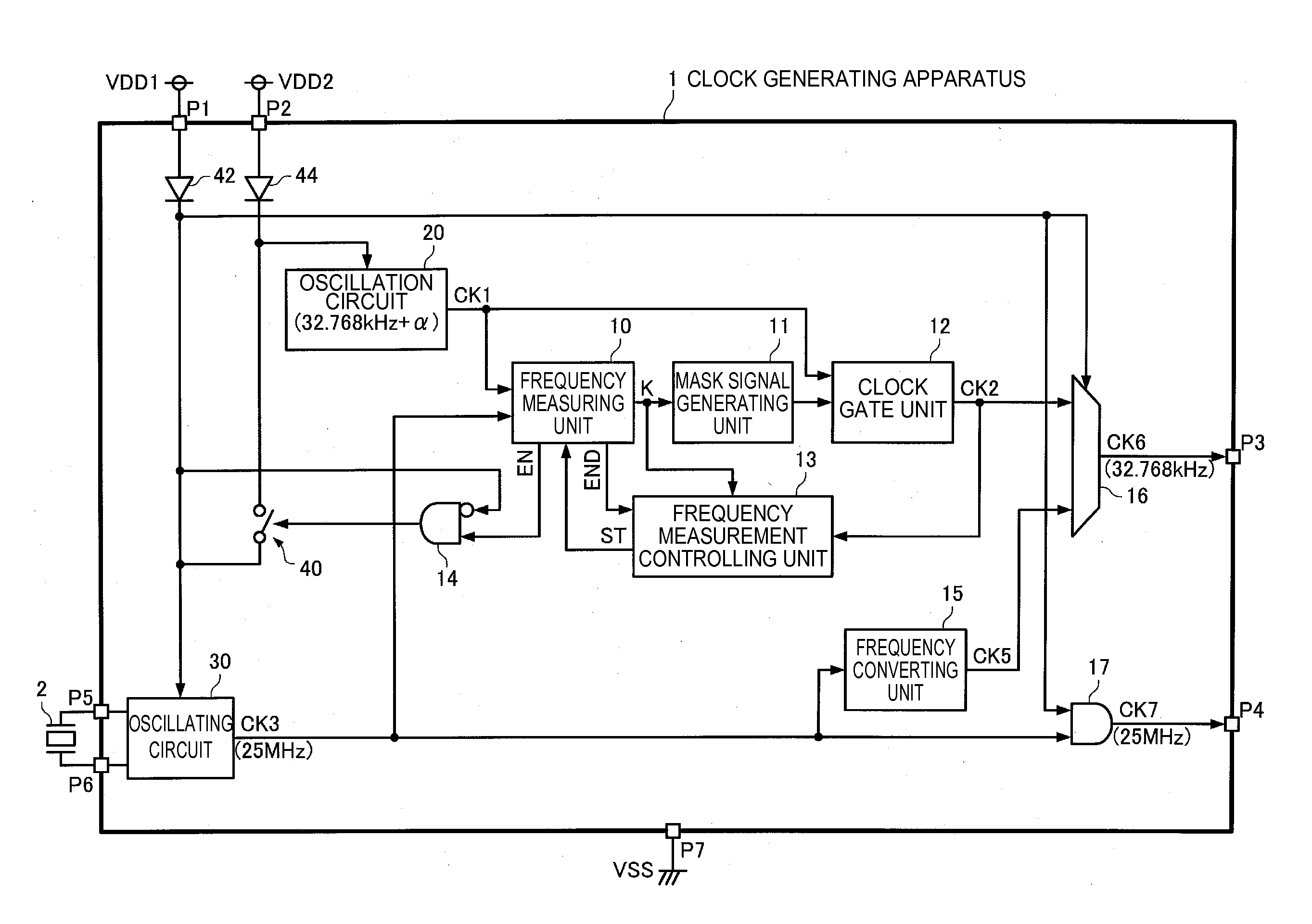
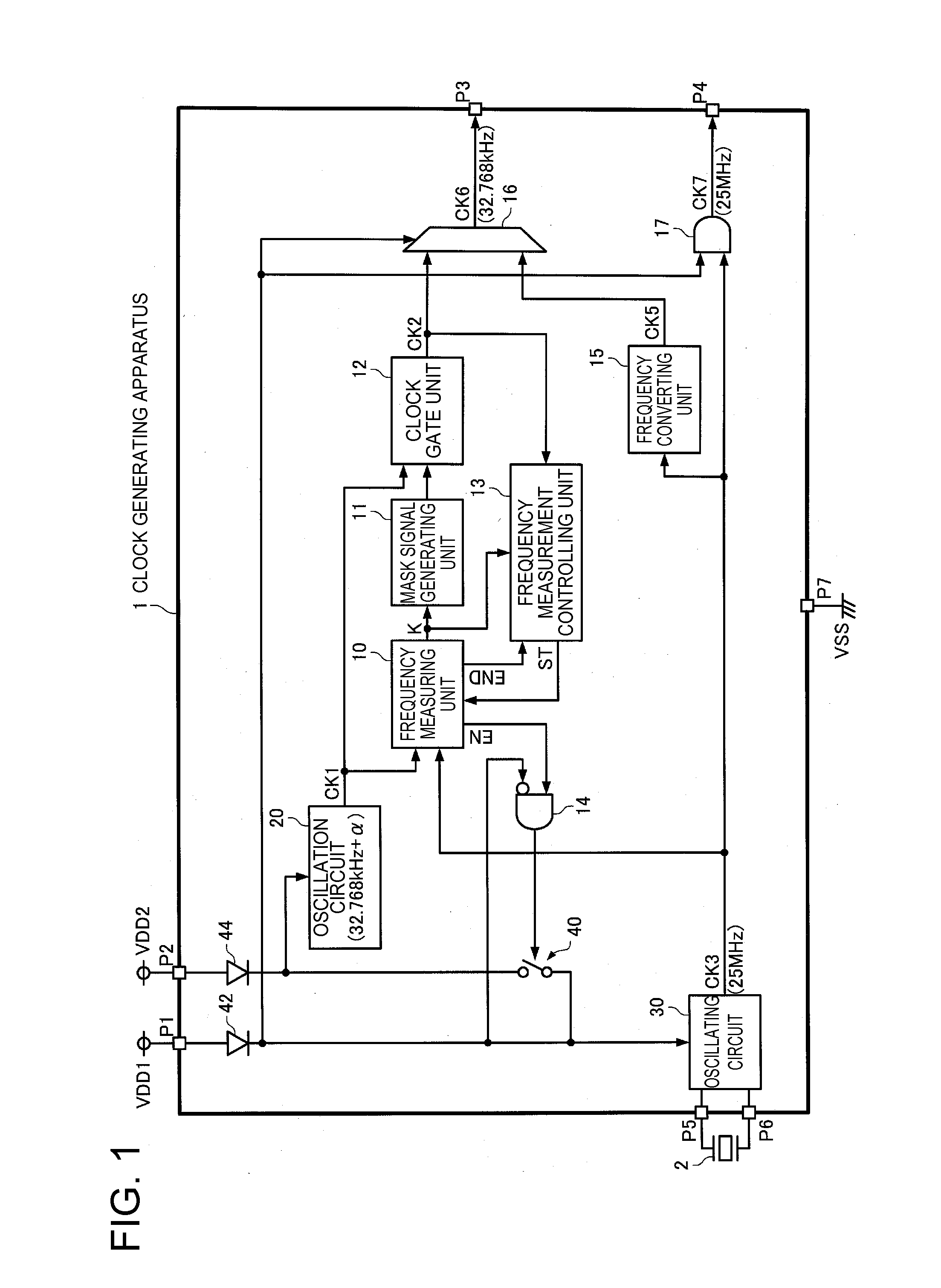
[0124]For example, according to the present embodiment, the clock generating device 1 realized by one IC is described as an example, but the clock generating device 1 may be realized by a plurality of ICs, or may be realized by connecting a plurality of discrete parts respectively corresponding to a plurality of components of the clock generating device 1 by wire on a board.
[0125]In addition, for example, in the clock generating device 1 according to the present embodiment, the clock signal CK5 is selected as the clock signal CK6 when the power supply voltage VDD1 of the primary power supply is supplied, and the clock signal CK2 is selected and output to the outside as the clock signal CK6 when the power supply voltage VDD1 of the primary power supply is not supplied. However, the clock generating devic...
PUM
 Abstract
Description
Claims
Application Information