Redundant steering system for guideway vehicle

a technology of guideway and steering system, which is applied in the direction of power rails, transportation and packaging, roads, etc., can solve the problems of inconvenience for passengers of vehicles, lack of desired degree of smoothness of vehicles, and several adverse consequences of automatic steering failures

Active Publication Date: 2010-11-09
HENDERSON JOY KIRSTON
View PDF9 Cites 19 Cited by
  • Summary
  • Abstract
  • Description
  • Claims
  • Application Information

AI Technical Summary

Benefits of technology

[0007]The backup steering device comprises an inner member configured for backup steering engagement with an inner side of the first web member and an outer member configured for backup steering engagement with an outer side of the first web member. The outer member is mechanically coupled to an actuator for selective positioning into and out of backup steering engagement. In one embodiment, the steering device comprises an actuator member and roller arm, wherein the actuator member is connected on one end to the actuator and pivotally connected on another end to the roller arm and the outer member is on a free end of the roller arm. Lateral displacement of the actuator arm by the actuator pivotingly and selectively moves the outer member into and out of position for backup steering engagement. An optional embodiment of the reference rail comprises a second web member extending at an angle from the base portion and defining a space between the first and second web member. A processor may be included configured to receive signals from a vehicle control system and control operation of the backup steering device.
[0008]In the preferred embodiment, the only use for the steering sensor is to supply steering error signals to the primary steering system servo controller. The steering sensor is not involved in any manner with commanding engagement or disengagement of the backup steering device. The selection of right or left hand steering sensors and right or left hand backup steering devices is made either by an on-board vehicle control system that is operated either automatically or on the basis of manual inputs from an on-board operator.
[0009]The backup mechanical steering device would be useful for vehicles operating with wheels or other suspension techniques, including magnetic levitation and air levitation either inside enclosed or open rails. In either case, the steering reference rail for the backup steering device is mounted at each side of the guideway. This steering reference rail may also be used as the steering reference for proximity sensing for the automated electromechanical steering system.

Problems solved by technology

In addition, the purely mechanical nature of the vehicle steering generally made it necessary to provide some dead zone between sets of steering rollers that caused the vehicles to sometimes tended to lack the desired degree of smoothness, sometimes causing some discomfort to vehicle passengers.
However, vehicles operating on fixed guideways and steering automatically based upon sensing proximity to fixed steering reference rails of the guideway need a positive backup mechanical means for steering in the event that reference rail position sensing or automatic steering controls fail.
Without such backup steering means, several adverse consequences can occur in the event of automatic steering failures.
Steering failure can result in the vehicle crashing sideways into guideway components such as electric power supply rails located at the sides of the guideway and thereby causing damage to the guideway and vehicle.
Steering failure can result in the vehicle running off of the guideway with potential for serious and even fatal consequences for vehicle passengers.
In cases wherein the vehicle must follow either the left or right side steering rail during switching at switch “Y” points between guideways, absence of such backup mechanical steering means engaged on the same side as the steering reference rail could cause the vehicle to lose control and cause a serious crash.

Method used


Image

  • Redundant steering system for guideway vehicle
  • Redundant steering system for guideway vehicle
  • Redundant steering system for guideway vehicle

Examples


Embodiment Construction

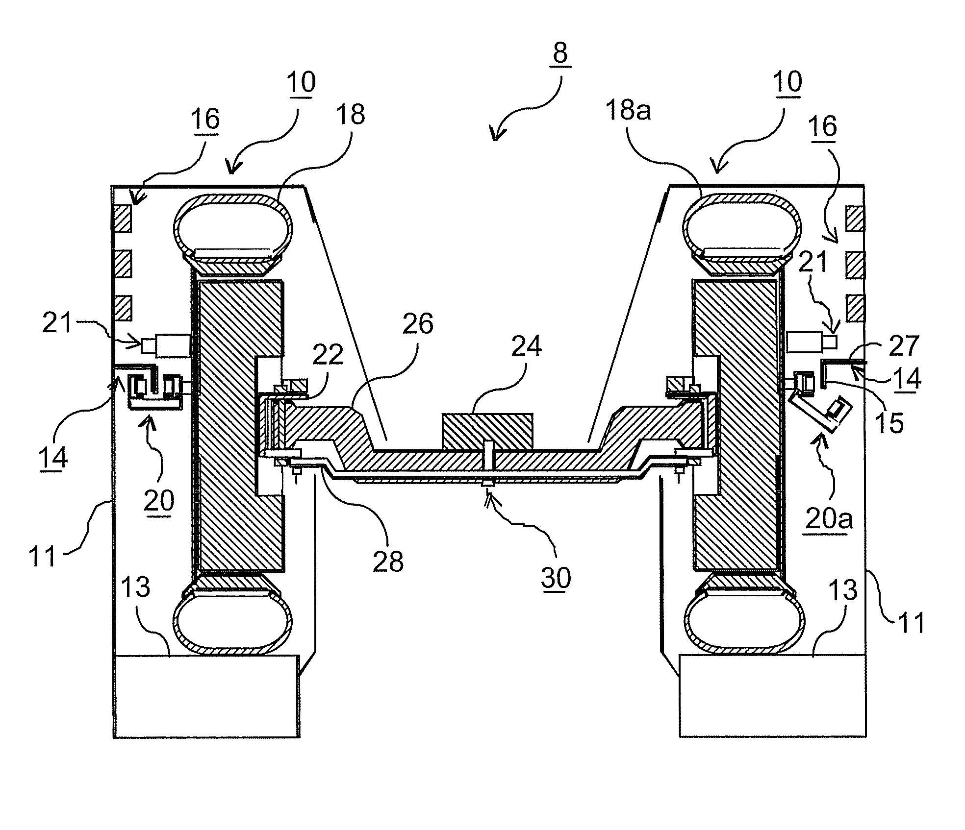
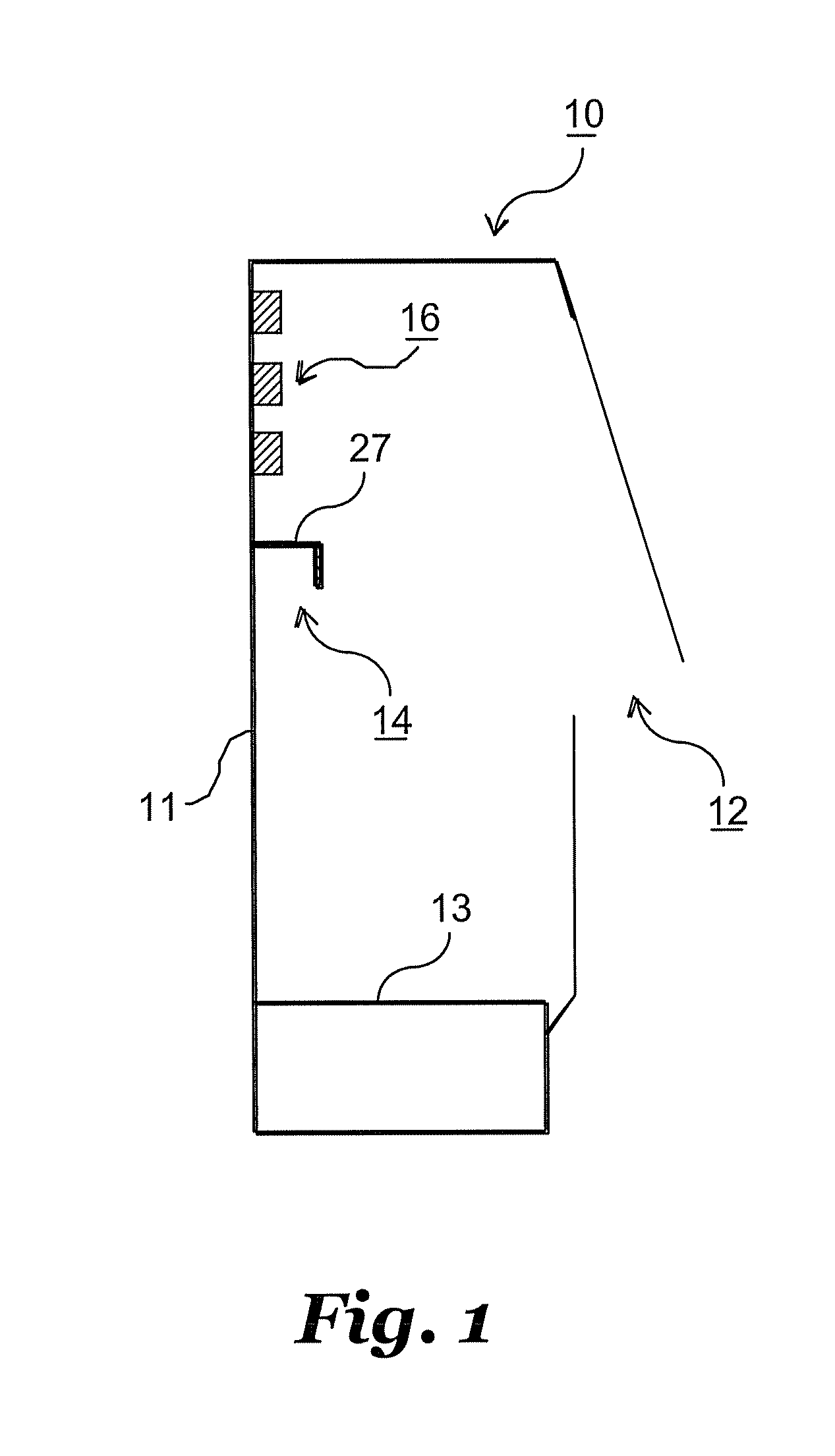
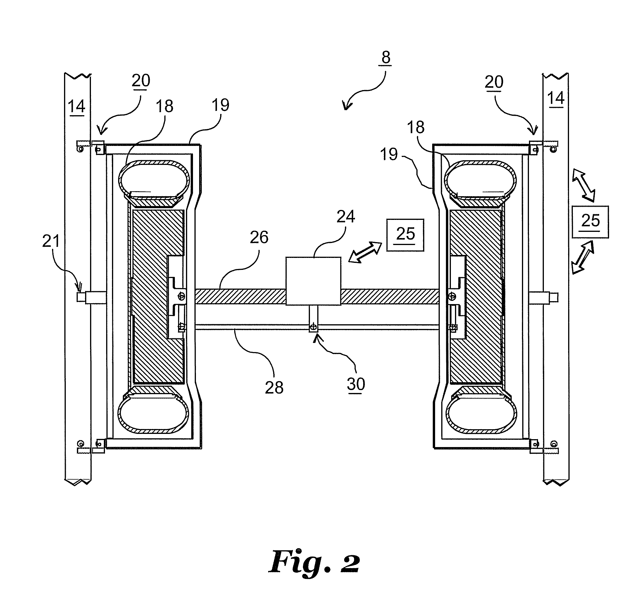
[0018]With reference now to FIG. 1, one embodiment of a rail tube 10 is shown in a side cross sectional view. As noted above, a rail tube makes up a portion of a guideway used in directing individual either guideway-captive or dualmode vehicles or vehicles associated with a guideway-captive train or dualmode tram systems. The rail tube 10 comprises an outer housing 11 through which associated wheels (not shown) of a vehicle are guided when traveling along the associated guideway. A base 13 is shown on the lower end of the housing 11 and configured for supporting the vehicle wheels / tires. The vehicle may be self powered or motivated by electrical power from power supply rails 16 running along the inside of the housing 11. A steering reference rail 14 is shown affixed to a portion of the inside of the housing 11. In this embodiment, the steering reference rail 14 comprises a base portion 27 aligned substantially perpendicular to a sidewall of the housing 11 and a vertical web member 1...


PUM


Abstract

A guideway system and method of operating a guideway is included comprising a guideway with entrance and exit ramps and vehicles having both a smooth, servo-based primary steering systems based upon proximity sensing of the side of the guideway and a backup mechanical steering system. The backup steering system is selectively engaged and disengaged based on location with respect to the entrance and exit ramps and provides vehicle wheel steering in the event of a failure of the primary servo steering system. The backup steering comprises one or more vertical members affixed to the guideway and one or more steering elements engageable with the member(s). The elements may be pivoted into and out of backup steering engagement.

Description

CROSS-REFERENCE TO RELATED APPLICATION[0001]This application claims priority to provisional application Ser. No. 60 / 875,499, filed Dec. 18, 2006.FIELD OF THE INVENTION[0002]The present disclosure relates in general to guided vehicles and more specifically relates to a redundant manner of steering the guided vehicle. The disclosure also relates to vehicles, trains or trams containing multiple vehicles coupled together that are operable either only on elevated guideways or on both conventional roadways and on elevated guideways.BACKGROUND OF THE INVENTION[0003]Several previous vehicles operated on fixed guideways that do not use flanged railroad-style wheels have employed some sort of steering rails mounted at each side of the guideway. These vehicles have generally employed sets of rollers at each side that were selectively engaged with the steering rails to rotate in contact with the rails as a purely mechanical means of steering the vehicle. Because in such cases the steering rolle...

Claims


Application Information

Patent Timeline
Patent Type & Authority Patents(United States)
IPC IPC(8): E01B7/00
CPCB61B5/02B61B15/00B62D1/265
Inventor HENDERSON, JOY KIRSTON
Owner HENDERSON JOY KIRSTON
Why Eureka
Try Eureka