
Apparatus and methods for proximity sensing circuitry

a proximity sensing circuit and apparatus technology, applied in the field of sensors, can solve the problems of parasitic reduction of energy oscillation, less accurate measurement of a target in proximity to the sensor, and resistance of the switch not contributing to a parasitic change in quality factor or time constan

Active Publication Date: 2009-06-04
ROCKWELL AUTOMATION TECH
View PDF4 Cites 80 Cited by
  • Summary
  • Abstract
  • Description
  • Claims
  • Application Information

AI Technical Summary

Benefits of technology

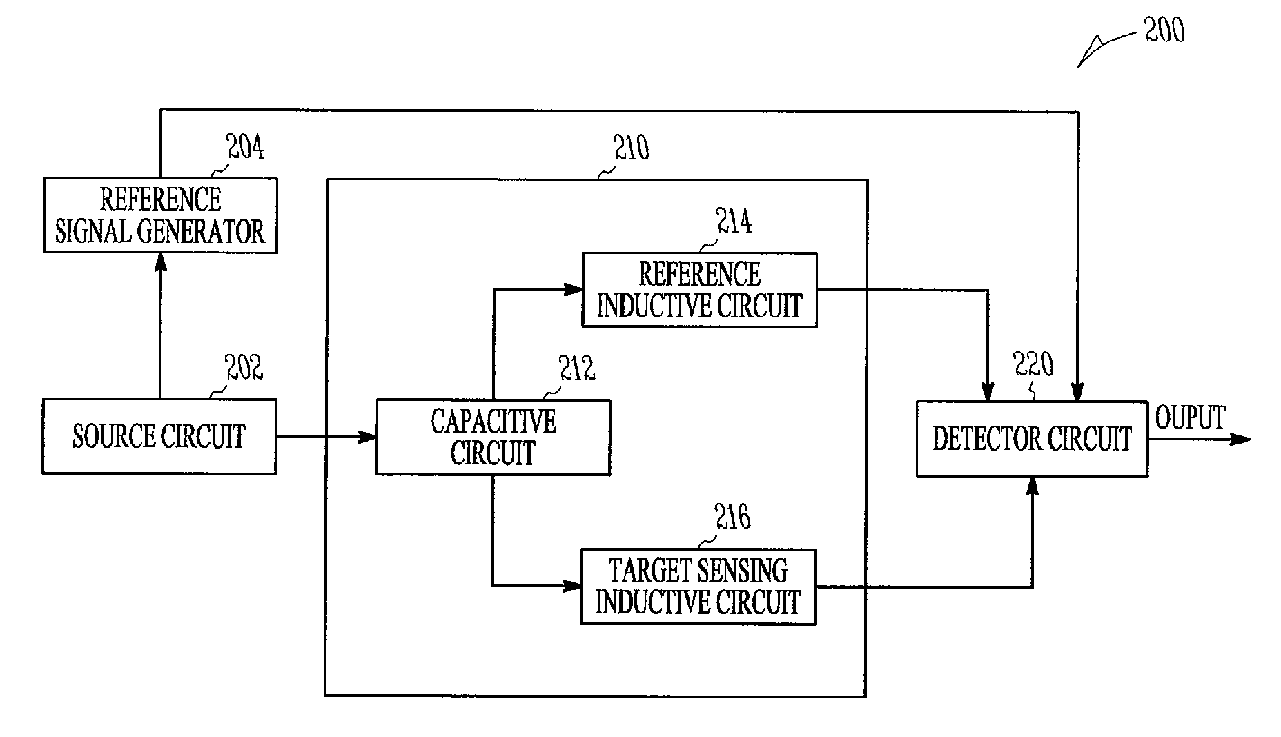
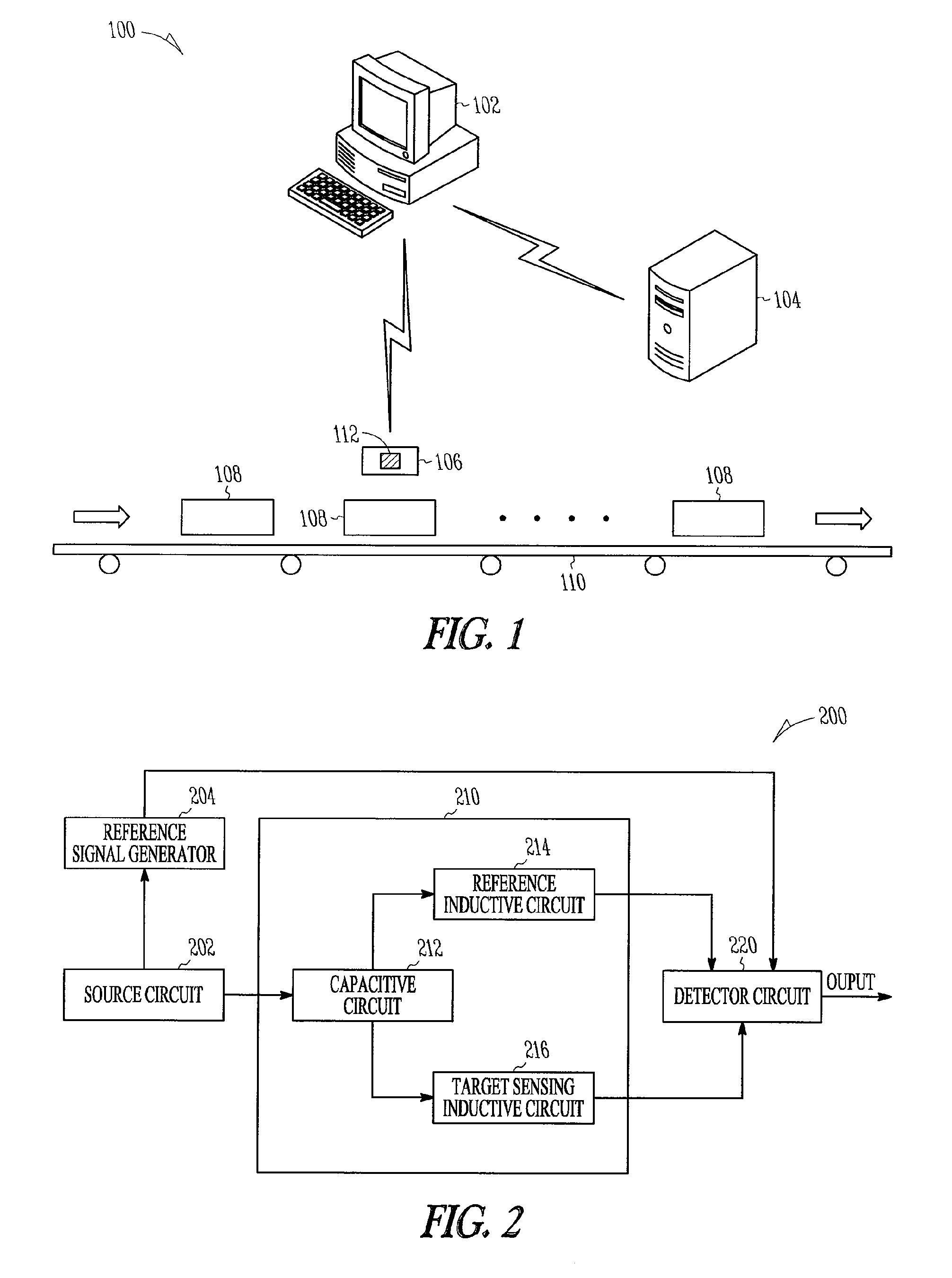
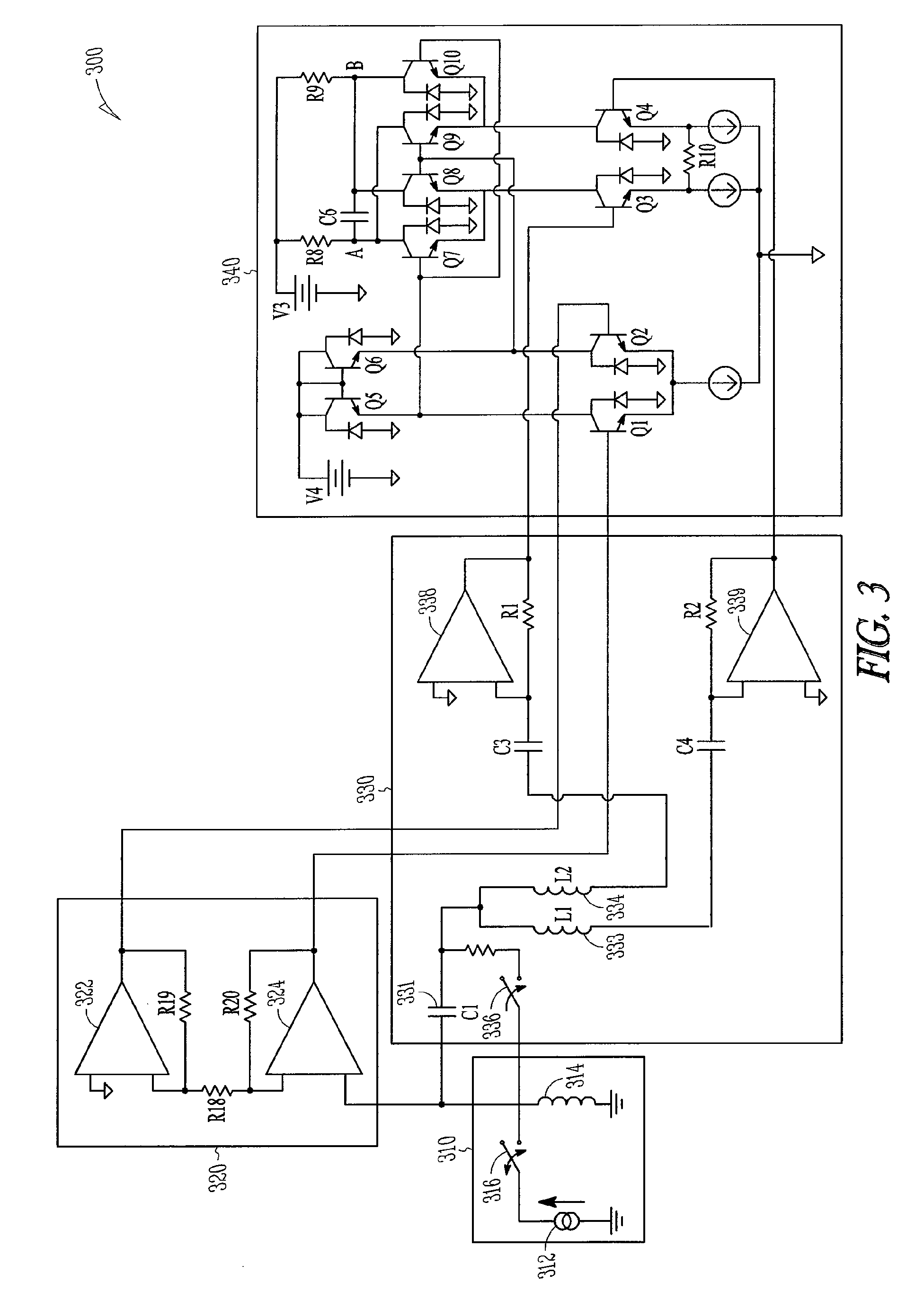
[0005]In an embodiment, a dynamic control system includes a processor and an inductive proximity sensor coupled to the processor. The inductive proximity sensor includes a source circuit comprising at least one of an inductive element and a step current source. The inductive proximity sensor also includes a resonator coupled to the source circuit. The resonator includes a resonant portion and a target sensing portion. The proximity sensor also includes a plurality of transimpedance amplifiers coupled to the res

Problems solved by technology

A drawback to the Wheatstone bridge is that only a portion of the target sensing and reference inductive signals are utilized, which can cause a less accurate measurement of a target in proximity to the sensor.
With this configuration, the intrinsic resistance of the switch can degrade the quality factor of the resonant portion of the inductive sensor thereby causing a parasitic reduction in energy oscillations.
Because the switch is not located within the path of the resonant circuit, the resistance of the switch cannot contribute a parasitic change in quality factor or time constant.
In either case, since the switching circuit is not located in the resonant path, an associated parasitic switching resistance cannot degrade the quality factor of the resonator.
Cracks in the target metal can cause additional losses in the eddy currents generated.
The accuracy of such an inductive proximity sensor can be limited by the number of off-resonance frequency components generated by its energizing source.

Method used


Image

  • Apparatus and methods for proximity sensing circuitry
  • Apparatus and methods for proximity sensing circuitry
  • Apparatus and methods for proximity sensing circuitry

Examples


Embodiment Construction

[0003]In an embodiment, a proximity sensor includes a resonator having bifurcated inductance. The resonator includes a reference portion and a target sensing portion. The proximity sensor also includes a plurality of transimpedance amplifiers coupled to the resonator at the reference portion and the target sensing portion. The proximity sensor also includes a detector coupled to an output of the transimpedance amplifiers. The detector is configured to provide a differential signal associated with an electromagnetic field interacting with a metal.

[0004]In an embodiment, a method of operating an inductive proximity sensor includes charging an inductive current source to a steady state value and initiating transfer of energy from the inductive current source to a resonant circuit. The resonant circuit includes a reference portion and a target sensing portion. The method also includes generating current oscillations in the reference portion and the target sensing portion, and sensing th...


PUM


Abstract

An inductive proximity sensor is disclosed. The proximity sensor includes a resonator with a bifurcated inductance coupled to a plurality of transimpedance amplifiers. A portion of the resonator is configured to generate eddy currents in a target containing metal. In various embodiments, the transimpedance amplifiers provide signals associated with eddy currents to a synchronous detector. Apparatus and methods for operating the inductive proximity sensor are disclosed.

Description

TECHNICAL FIELD[0001]The various embodiments described herein relate generally to sensors, including inductive proximity sensors.BACKGROUND[0002]An automated system can enable product manufacturing at greater speeds, lower cost and with a higher safety margin than is generally possible with a manually operated system. Many automated systems employ sensors to guide the movement of the various interworking parts that make up the system. Since the desire to lower product manufacturing costs will likely continue to grow, so will the use of automated systems. Therefore, the number of sensors can be expected to increase.BRIEF SUMMARY OF THE EMBODIMENTS[0003]In an embodiment, a proximity sensor includes a resonator having bifurcated inductance. The resonator includes a reference portion and a target sensing portion. The proximity sensor also includes a plurality of transimpedance amplifiers coupled to the resonator at the reference portion and the target sensing portion. The proximity sens...

Claims


Application Information

Patent Timeline
IPC IPC(8): G01B7/14
CPCG01B7/023
Inventor ROLLINS, GEORGE E.KULKARNI, PRACHI S.
Owner ROCKWELL AUTOMATION TECH
Learn More