
Lighting device and liquid crystal display using it

a technology of liquid crystal display and light source, which is applied in the direction of lighting device details, lighting and heating apparatus, instruments, etc., can solve the problems of low light utilization efficiency, high probability of non-uniform light emission, and decrease in light emission quantity, so as to reduce the probability of non-uniform light emission, and eliminate non-uniform light emission.

Inactive Publication Date: 2010-11-09
HITACHI LTD
View PDF24 Cites 1 Cited by
  • Summary
  • Abstract
  • Description
  • Claims
  • Application Information

AI Technical Summary

Benefits of technology

[0022]The present invention has an object of solving the above-described problems. More specifically, the object of the invention is to provide a high-performance backlight which can achieve high color reproductivity, high moving picture quality and the like or a backlight having a small number of light sources with less non-uniformity in light emission and at a low cost.
[0026]The lighting device according to the invention can eliminate non-uniformity in light emission at a low cost by controlling the in-plane transmittance distribution with the slits in the one surface of the optical film. When the lighting device is used as a liquid crystal display, it has less non-uniformity in light emission and can be provided at a low cost, while being a high-performance backlight which can achieve high moving picture quality.

Problems solved by technology

However, since efficiency for light utilization is low, and the number of light sources which can be arranged is limited in order to reduce the thickness, the quantity of emitted light decreases.
However, since there are wide variations in light emitting property among existing LEDs, and LEDs which are a point light source are used in the bottom emitting type configuration in which a distance for scattering and uniformization of light is short, non-uniformity in light emission is highly likely to occur.
Similarly, a reduction in the number of light sources such as a CCFL and LED for a lower cost causes non-uniformity.
In the meantime, the prices for displays using LCDs, i.e., notebook computers, liquid crystal monitors, liquid crystal televisions and the like are now rapidly falling.
This requires highly advanced manufacturing process technology and increases the cost.
This also leads to a higher cost.
As described above, improvement in the performance of a backlight such as use of a primary color LED for enhancement of color reproductivity or adoption of a partition structure intended to improve moving picture quality leads to an increase in thickness for elimination of non-uniformity in light emission or an increase in the cost of the backlight.

Method used


Image

  • Lighting device and liquid crystal display using it
  • Lighting device and liquid crystal display using it
  • Lighting device and liquid crystal display using it

Examples


Embodiment Construction

[0045]Embodiments of the invention will be described below with reference to the drawings.

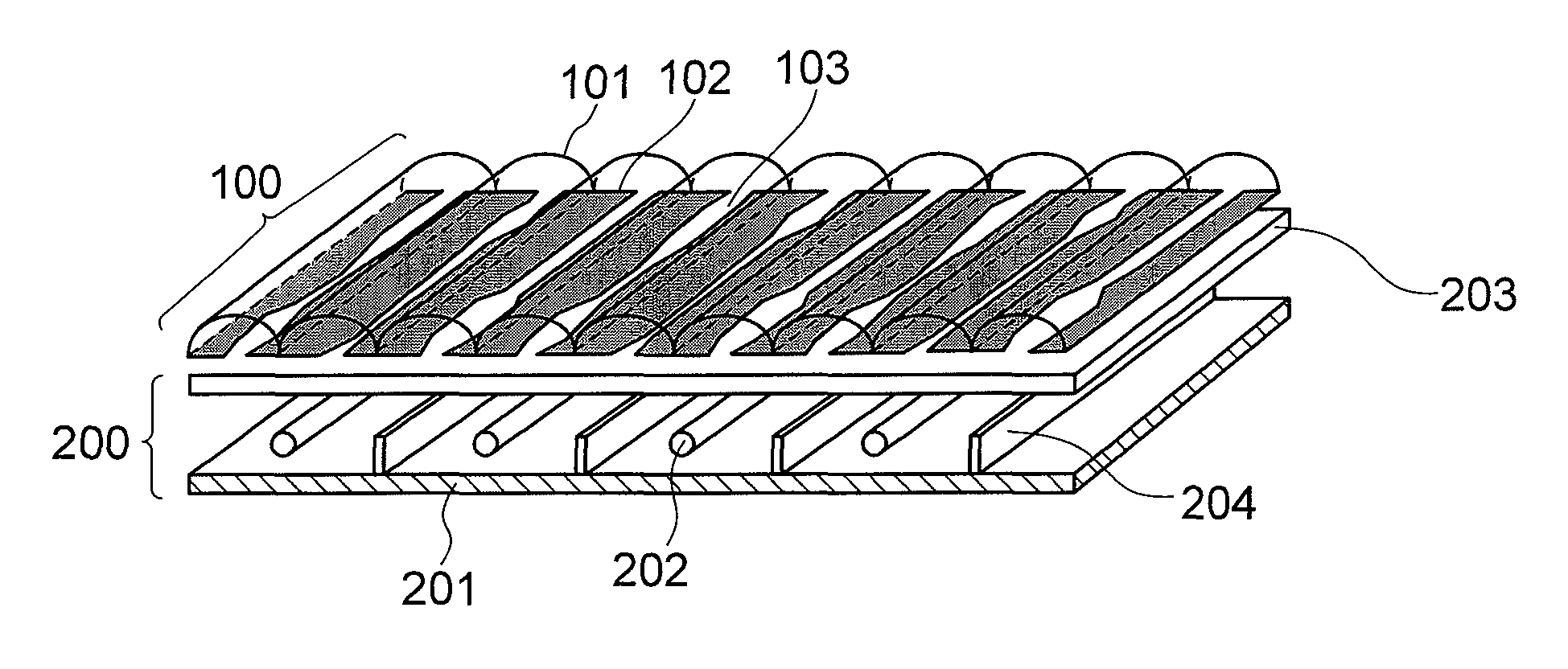
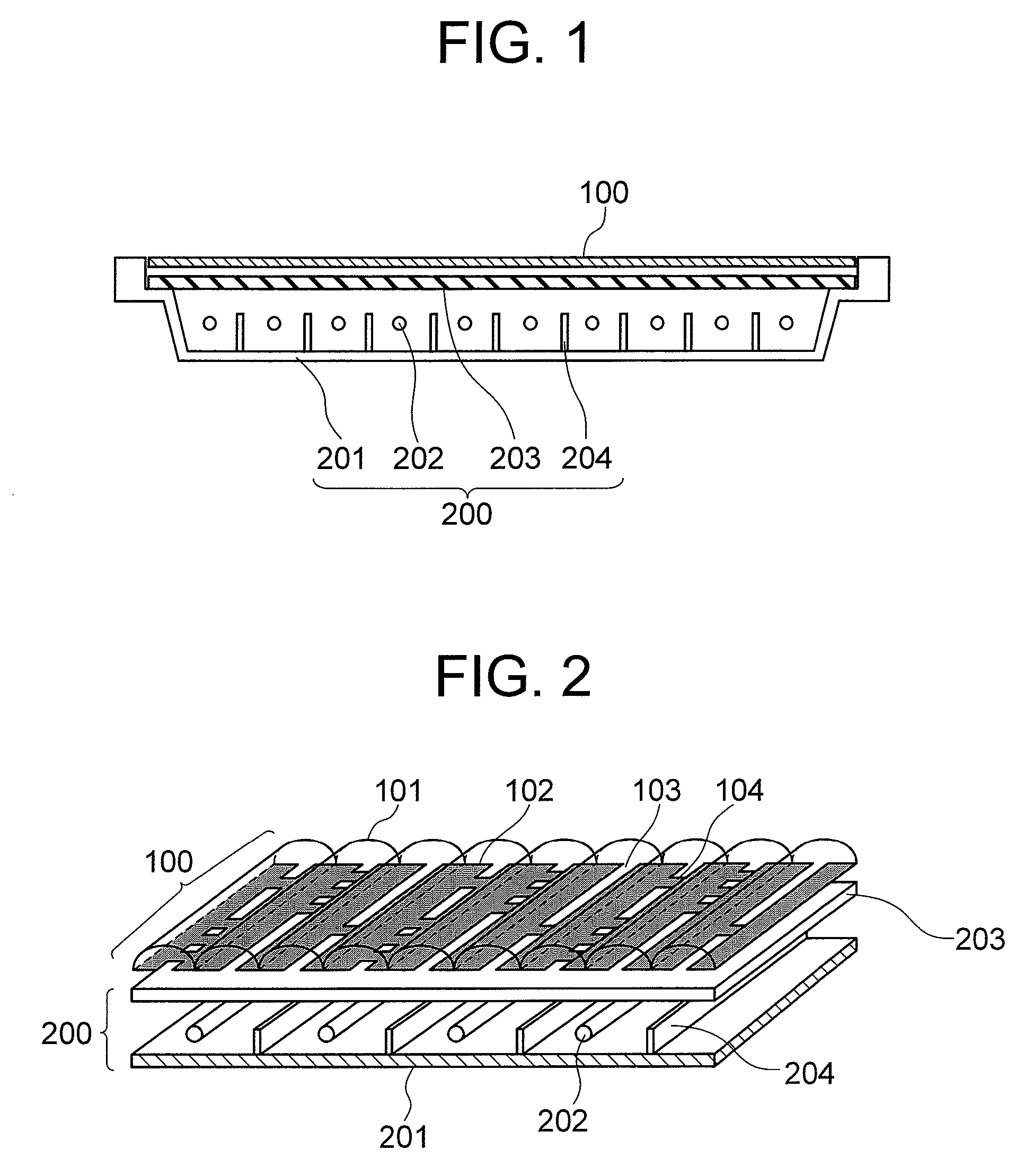
[0046]FIG. 1 shows a sectional view of the lighting device according to the first embodiment of the invention. The lighting device of this embodiment is mainly comprised of a backlight section 200 and an optical film (or optical plate) 100. The backlight section 200 uses ten CCFLs 202 in a backlight frame 201. The CCFLs 202 can be controlled between a light emission state and a non-light emission state independently of each other. Optical partitions 204 are arranged between the CCFLs 202 to divide a light emission area into areas and limit leakage of light between the areas.

[0047]A light scattering plate 203 is arranged above the CCFLs 202 to be in contact with the backlight frame 201. The light scattering plate 203 scatters and reflects incident light, and part of the light is returned to the incident side.

[0048]Although not shown in FIG. 1, the inner surface of the backlight frame 201 is cove...


PUM

PropertyMeasurementUnit
in-plane transmittance distributionaaaaaaaaaa
transmittance distributionaaaaaaaaaa
relative light intensity distributionaaaaaaaaaa

Abstract

A lighting device for emitting light in a planar manner comprises a backlight section having non-uniformity in light emission in a plane and an optical film having an in-plane transmittance distribution compensating for the non-uniformity in light emission. The optical film has a plurality of slits allowing light to pass through and controls the in-plane transmittance distribution by varying the shapes of slit openings. Widths of the slits are fixed, closed portions are provided in a longitudinal direction, and the in-plane transmittance distribution is controlled by the ratio of the closed portions to the slits. A part of the optical film other than the slits is a light shielding layer, and a surface on the light source side of the light shielding layer scatters and reflects light. Each value in the in-plane transmittance distribution of the optical film is smaller than the reciprocal of a corresponding value in a light intensity distribution of the backlight section. A surface opposite to a surface on the light source side of the optical film has a cylindrical lens structure focused on the slits. Non-uniformity in light emission in the lighting device such as a backlight used in a liquid crystal display is eliminated at a low cost.

Description

INCORPORATION BY REFERENCE[0001]The present application claims priority from Japanese application JP2006-002293 filed on Jan. 10, 2006, the content of which is hereby incorporated by reference into this application.BACKGROUND OF THE INVENTION[0002]The present invention relates to a liquid crystal display which has a good display quality and is low-cost.[0003]Conventional liquid crystal displays will be explained below. Although CRTs had been the mainstream of displays, active matrix-type liquid crystal displays (hereinafter referred to as LCDs) have been becoming prevalent in these years. The LCD is a display which utilizes the light transmittance of a liquid crystal, and does not emit light by itself. The LCD produces a gray scale display by controlling the emission of a backlight provided on the back among a light-transmitting state, a light-blocking state, and an intermediate state between the two states.[0004]The backlight on the back uses, as a light source, a cold cathode tube...

Claims


Application Information

Patent Timeline
Patent Type & Authority Patents(United States)
IPC IPC(8): G02F1/1335
CPCG02F1/133606G02F1/133611G02F2001/133607G02F1/133607
Inventor YAMAMOTO, TSUNENORIKONDO, KATSUMI
Owner HITACHI LTD
Learn More