
Liquid crystal display device

a liquid crystal display and display device technology, applied in the field of liquid crystal display devices, can solve the problems of loss of uniformity of color and light emission, waste of light-emitting diodes, and color variation of emission by products, and achieve the effect of improving image quality

Active Publication Date: 2010-07-29
PANASONIC LIQUID CRYSTAL DISPLAY CO LTD +1
View PDF1 Cites 3 Cited by
  • Summary
  • Abstract
  • Description
  • Claims
  • Application Information

AI Technical Summary

Benefits of technology

[0010]An object of the invention is to solve such problems described above, and to provide a liquid crystal display device that offers, although using white light-emitting diodes having the problem of impairing the uniformity of color of emission, higher-quality display images using a backlight with less non-uniformity of color and light emission as a whole, and prevents the increase of the manufacturing cost.
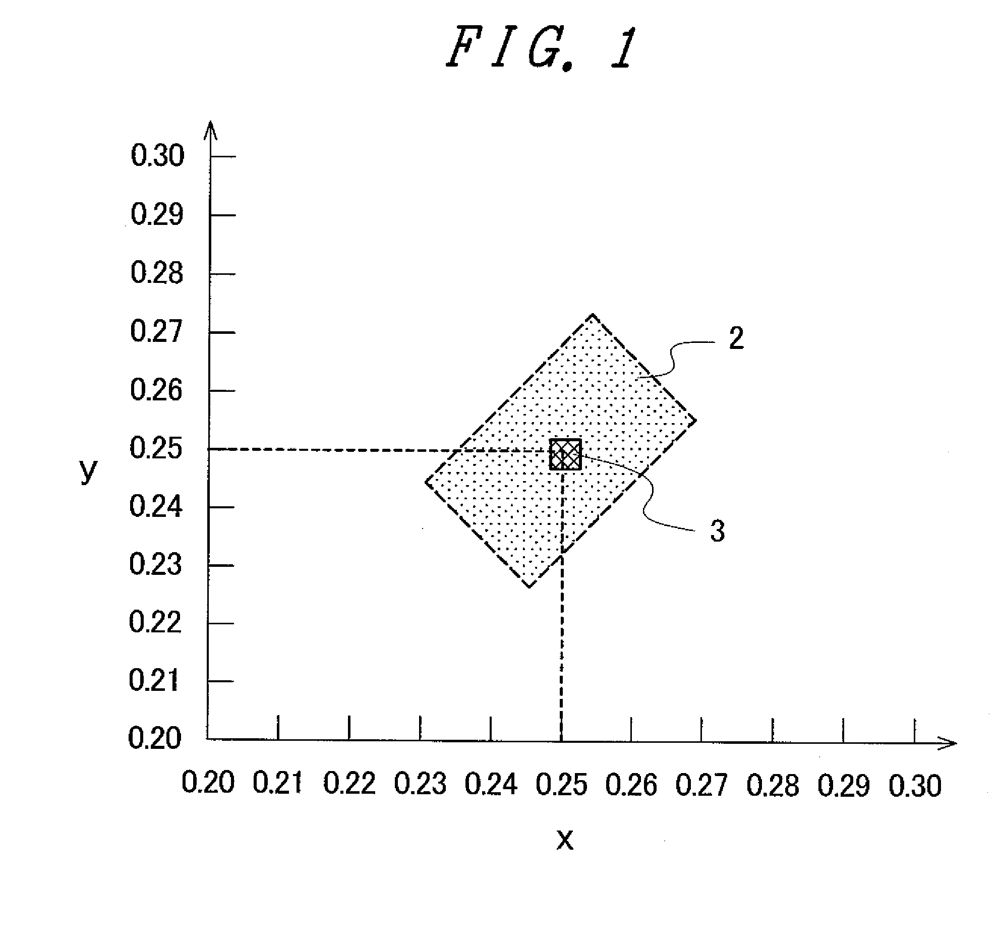
[0018]With the liquid crystal display device described in 1 above, based on a chromaticity coordinate value representing a color of emission identified for each of the white light-emitting diodes, the white light-emitting diodes are selectively combined for arrangement in proximity in such a manner that a color of emission as a result of averaging over the white light-emitting diodes to be arranged in proximity takes a predetermined value of chromaticity coordinates. Accordingly, the resulting backlight can be with less non-uniformity of color of emission so that the resulting liquid crystal display device can be high in display quality. What is more, because the white light-emitting diodes having the problem of impairing the uniformity of color of emission can be used, the manufacturing cost can be favorably prevented from increasing.
[0019]With the configuration described in 2 above, based on the chromaticity coordinate value of the color of emission identified for each of the white light-emitting diodes, the white light-emitting diodes are classified into a plurality of groups depending on whether the coordinate values are close to each other or not, the white light-emitting diodes respectively selected specifically from the groups are placed in proximity as a combined unit, and by repeating such a unit placement, the white light-emitting diodes are arranged in the plane. This accordingly prevents the color of emission from varying among the combined units as such, thereby favorably leading to the backlight with less non-uniformity of color of emission in its entirety. What is more, because the white light-emitting diodes are selectively classified into a plurality of groups in advance, for assembling a backlight, there only needs to fixedly dispose sequentially a specific combined unit of the white light-emitting diodes selected from the respective groups onto a support substrate for supporting the light-emitting diodes. As such, the assembly of the backlight can be completed with the better efficiency.
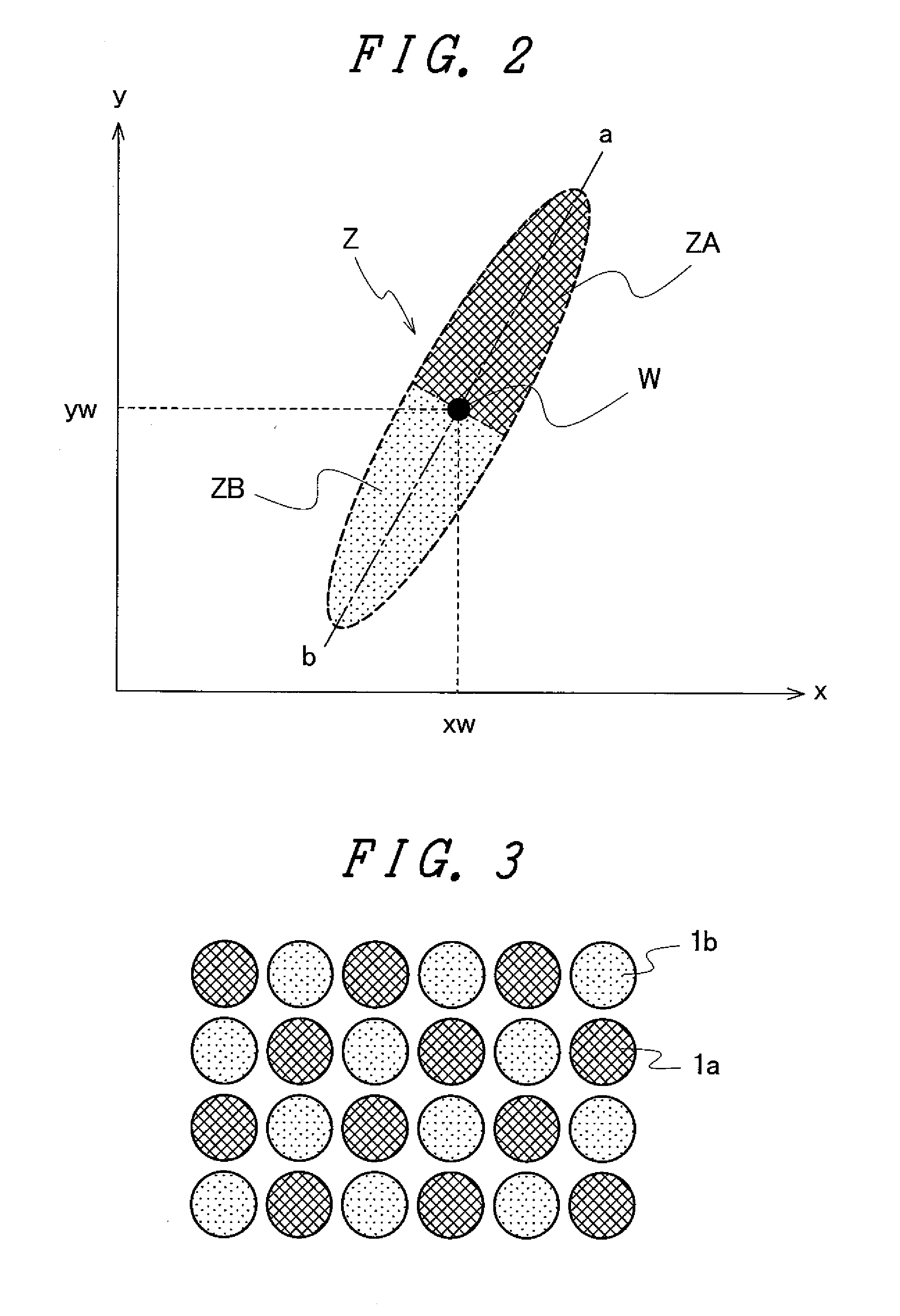
[0020]With the configuration described in 3 above, based on the chromaticity coordinate value of the color of emission identified for each of the white light-emitting diodes, the white light-emitting diodes are classified into two groups depending on whether the coordinate values are close to each other or not, and the white light-emitting diodes selected from the two groups are arranged alternately in a zigzag arrangement. Accordingly, the white light-emitting diodes of two types located in proximity cooperatively emit a light of a predetermined color, and such two types of the white light-emitting diodes are arranged in an alternate manner. With such a configuration, the resulting backlight can be with less non-uniformity of color of emission to a further degree so that the resulting liquid crystal display device can be high in display quality.
[0021]With the configuration described in 4 above, based on the chromaticity coordinate value of the color of emission identified for each of the white light-emitting diodes, the white light-emitting diodes are classified into three groups depending on whether the coordinate values are close to each other or not, and the white light-emitting diodes selected from the three groups are arranged alternately in a delta arrangement. Accordingly, the white light-emitting diodes of three types located in proximity cooperatively emit a light of a predetermined color, and such three types of the white light-emitting diodes are arranged in an alternate manner. With such a configuration, the resulting backlight can be with less non-uniformity of color of emission to a further degree so that the resulting liquid crystal display device can be high in display quality.
[0023]With the configuration described in 6 above, the white light-emitting diodes to be arranged in proximity are selectively combined in such a manner that an intensity of emission as a result of averaging over the white light-emitting diodes to be arranged in proximity takes a predetermined value. Accordingly, any possible variation to be observed in intensity of emission can be reduced so that the resulting liquid crystal display device can be higher in image quality.

Problems solved by technology

The problem with such a white light-emitting diode is that the color of emission varies by product.
As such, when a backlight is configured using a plurality of white light-emitting diodes, the uniformity of color and light emission is lost, e.g., the color of emission by the backlight looks different from part to part on the liquid crystal panel.
If this is the configuration, however, most of the white light-emitting diodes will go waste, and thus the resulting liquid crystal display device will be extremely high in cost.

Method used


Image

  • Liquid crystal display device
  • Liquid crystal display device
  • Liquid crystal display device

Examples


Embodiment Construction

[0031]Described below is the configuration of the invention in detail using a preferred example.

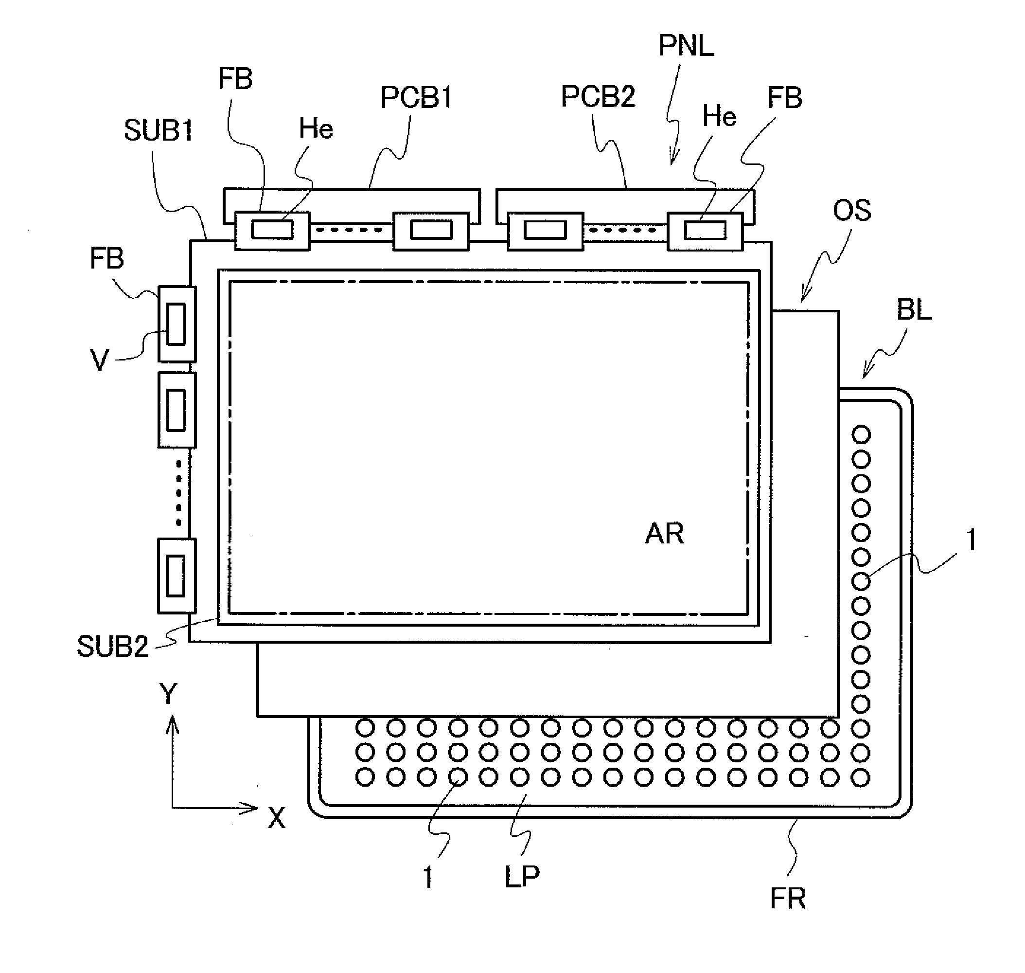
[0032]FIG. 7 is a schematic diagram showing the configuration of a liquid crystal display device to which the invention is applied. A liquid crystal display panel PNL is disposed on the side of a viewer, and on the rear of the liquid crystal display panel PNL, a sheet OS and a backlight BL are disposed in order.

[0033]The liquid crystal display panel PNL is provided with a pair of glass-made substrates SUB1 and SUB2 that are disposed to be parallel to each other, for example. These substrates SUB1 and SUB2 sandwich a liquid crystal material therebetween. On the respective surfaces of the substrates SUB1 and SUB2 facing the liquid crystal material, a plurality of pixels (not shown) arranged in a matrix are formed with the liquid crystal material serving as one configuration component, thereby enabling control over a transmittance of light on a pixel basis. The area formed with the pixels as...


PUM


Abstract

In a liquid crystal display device including a liquid crystal display panel, and a backlight disposed on the rear surface of the liquid crystal display panel, the backlight is provided with a plurality of white light-emitting diodes arranged in a plane opposing the liquid crystal display panel. Based on a chromaticity coordinate value representing a color of emission identified for each of the white light-emitting diodes, the white light-emitting diodes are selectively combined for arrangement in proximity in such a manner that the color of emission as a result of averaging over the white light-emitting diodes (1a, 1b) to be arranged in proximity takes a predetermined value of chromaticity coordinates. Accordingly, the resulting liquid crystal display device can offer, although using the white light-emitting diodes having the problem of impairing the uniformity of the color of emission, higher-quality display images using a backlight with less non-uniformity of color and light emission as a whole, and prevents the increase of the manufacturing cost.

Description

[0001]The present application claims priority from Japanese application JP 2009-015119 filed on Jan. 27, 2009, the content of which is hereby incorporated by reference into this application.BACKGROUND OF THE INVENTION[0002]1. Field of the Invention[0003]The present invention relates to a liquid crystal display device and, more specifically, to a liquid crystal display device using a backlight in which a plurality of white light-emitting diodes are systematically arranged in a planar view.[0004]2. Description of the Related Art[0005]A liquid crystal display device is generally provided with a backlight for illuminating a liquid crystal panel from the rear surface thereof. The backlight can be various types of light emission source, and is mainly exemplified by a fluorescent tube including a cold cathode tube, an external electrode fluorescent lamp, and others, a planar light source including an electroluminescent light source, and a point light source including a light-emitting diode...

Claims


Application Information

Patent Timeline
IPC IPC(8): G02F1/1335
CPCG02F1/133603G02F2001/133613G02F1/133609G02F1/133613
Inventor IMAJO, IKUKOOKE, RYUTAROYAMAZAKI, SACHIKOBABA, MASASHI
Owner PANASONIC LIQUID CRYSTAL DISPLAY CO LTD
Learn More