
Illumination optical apparatus and optical apparatus

a technology of optical apparatus and illumination optical apparatus, which is applied in the field of illumination optical apparatus and optical apparatus, can solve the problems of complex optical system, inability to employ the above-described known illumination optical apparatus, and high apparatus cost, and achieve the effect of less illumination non-uniformity and efficient light collection

Inactive Publication Date: 2010-06-08
OLYMPUS CORP
View PDF10 Cites 3 Cited by
  • Summary
  • Abstract
  • Description
  • Claims
  • Application Information

AI Technical Summary

Benefits of technology

[0006]The present invention has been conceived in light of the above-described circumstances, and it is an object of the present invention to provide an illumination optical apparatus and an optical apparatus using this illumination optical apparatus that are capable of efficiently collecting light emitted from light sources for illumination with less illumination nonuniformity, without having to employ a complicated structure or imposing restrictions upon the shapes and the layout of the light sources and the shape of the fly-eye lens. Preferably, another object of the present invention is to provide an illumination optical apparatus and an optical apparatus using this illumination optical apparatus which allow appropriate light sources to be selected according to, for example, the properties of the specimen to be examined.

Problems solved by technology

This illumination optical apparatus, however, is problematic in that, for example, it requires a beam splitting system, which causes the optical system to become complicated.
The illumination optical apparatus has another disadvantage in that since high parts precision is required to achieve the desired performance, the apparatus becomes very costly.
However, such a structure cannot be employed in the above-described known illumination optical apparatus.

Method used


Image

  • Illumination optical apparatus and optical apparatus
  • Illumination optical apparatus and optical apparatus
  • Illumination optical apparatus and optical apparatus

Examples


first embodiment

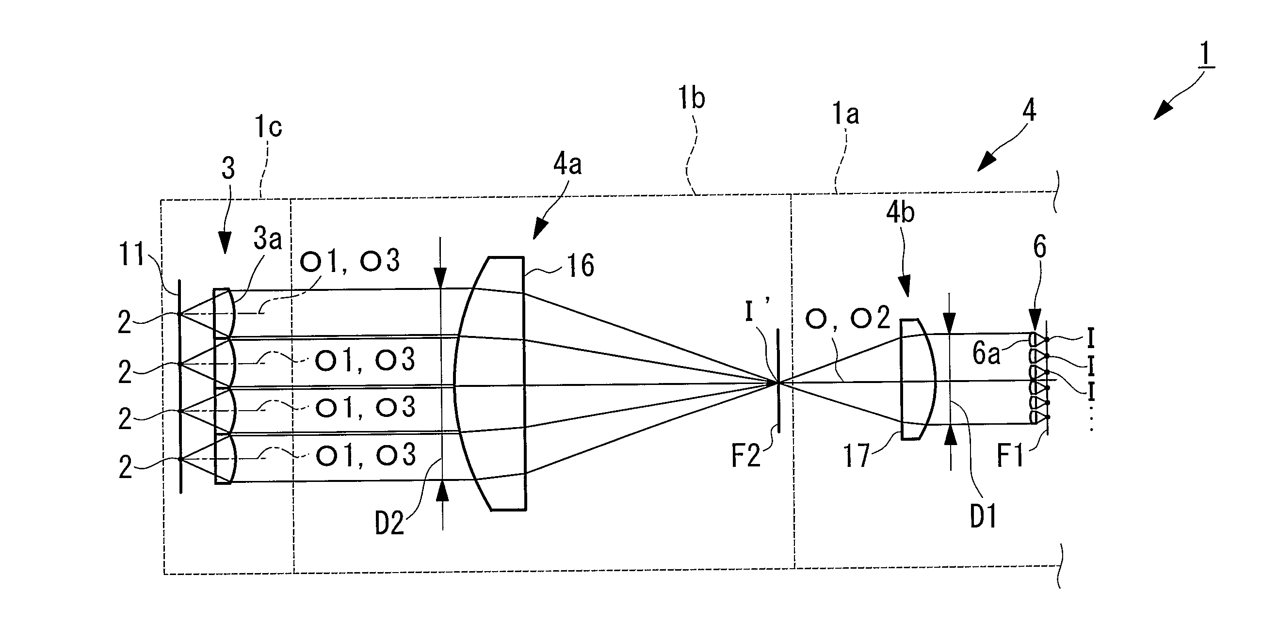
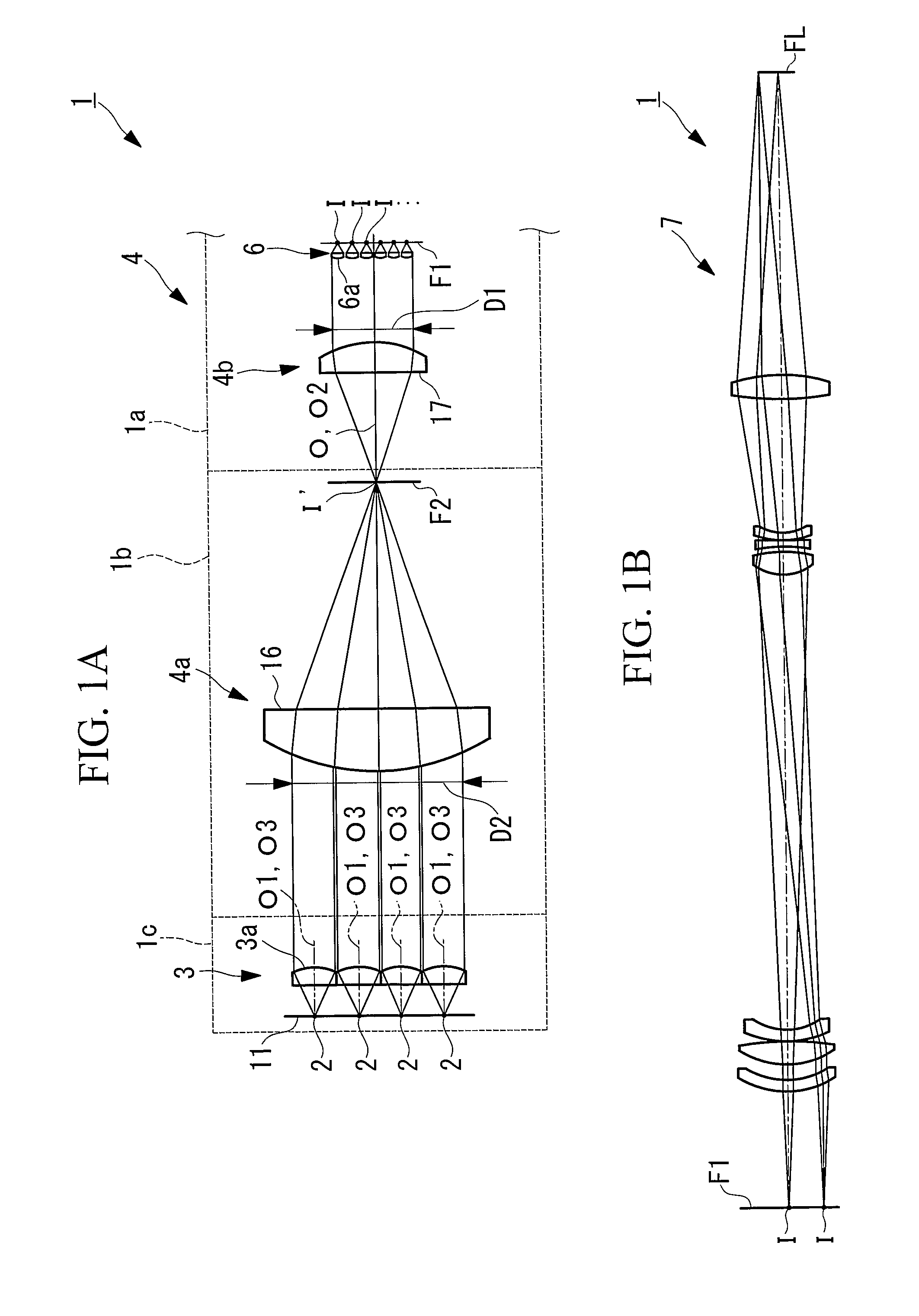
[0052]An optical apparatus according to the present invention is an optical apparatus including an illumination optical apparatus according to the present invention. More specifically, the optical apparatus according to the present invention is, for example, a projection apparatus having a projection optical system for projecting an image with the illumination optical apparatus according to the present invention as a light source; an exposure apparatus having a projection optical system for projecting a mask pattern onto a photosensitive member by using the illumination optical apparatus according to the present invention; and a microscope having an observation optical system for examining a target object illuminated with the illumination optical apparatus according to the present invention.

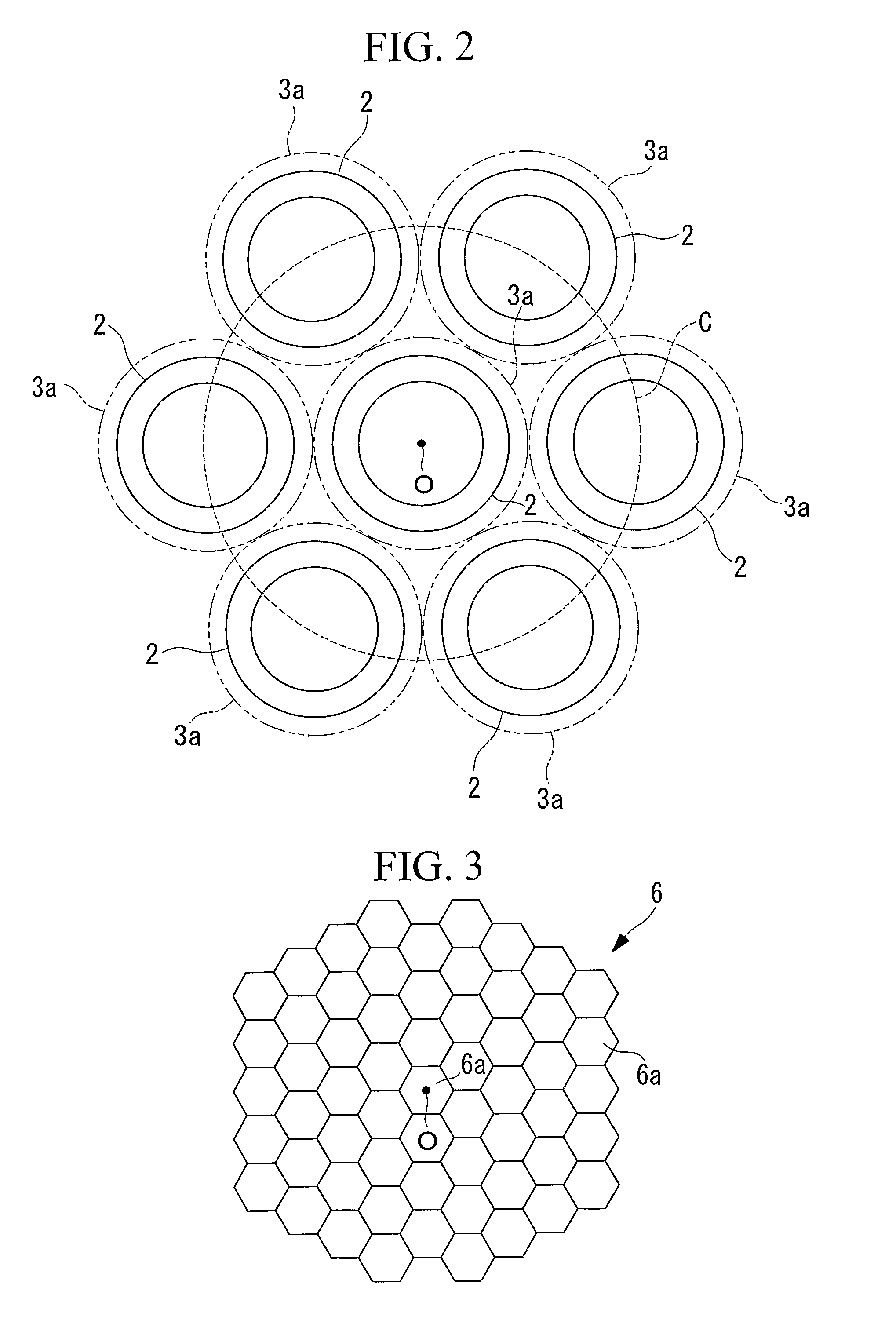
[0053]This embodiment is described by way of an example where the present invention is applied to a microscope having an illumination optical apparatus 1, shown in FIG. 1A and FIG. 1B, and an obs...

second embodiment

[0099]A second embodiment of the present invention will now be described.

[0100]An optical apparatus according to this embodiment illuminates an illumination surface by using an illumination optical apparatus 21 shown in FIG. 8.

[0101]The illumination optical apparatus 21 is mainly characterized in that it is provided with an afocal optical system 22, instead of the afocal optical system 4 of the illumination optical apparatus 1 described in the first embodiment.

[0102]The afocal optical system 22 includes a first group 22a arranged adjacent to the plurality of light-emitting sections 2 and a second group 22b arranged adjacent to the fly-eye lens 6.

[0103]In this embodiment, the first group 22a is composed of a convex lens 23, and the second group 22b is composed of a concave lens 24. As a result, the first group 22a is constructed so as to adjust the cross-sectional area of a beam without focusing the images from the plurality of light-emitting sections 2 between the first group 22a an...


PUM


Abstract

There are provided an illumination optical apparatus and an optical apparatus using this illumination optical apparatus that are capable of efficiently collecting light emitted from a light-emitting section for illumination with less illumination nonuniformity, without having to employ a complicated structure. There are provided a light-emitting sections; a lens system for converting a diverging beam emitted from the light-emitting section into a beam of collimated light; an afocal optical system for adjusting the cross-sectional area of a beam of collimated light obtained by the lens array; a fly-eye lens for forming a plurality of light-source images from the collimated light whose cross-sectional area is adjusted by the afocal optical system; and a Koehler illumination optical system that uses the plurality of light-source images formed by the fly-eye lens as a light source.

Description

TECHNICAL FIELD[0001]The present invention relates to an illumination optical apparatus, such as a projection apparatus, an exposure apparatus, and a microscope, and to an optical apparatus using such an illumination optical apparatus.BACKGROUND ART[0002]In an illumination optical system of an optical apparatus, such as a projection apparatus, an exposure apparatus, and a microscope, the ability to illuminate the entire illumination area uniformly and with sufficiently bright light is required.[0003]Known illumination optical apparatuses for realizing such illumination include, for example, the illumination apparatus described in Japanese Unexamined Patent Application Publication No. 6-349710 (refer to the section from line 31 in column 10 to line 30 in column 11, as well as FIG. 7).[0004]This illumination optical apparatus improves, for example, the power of illumination light and the illuminance uniformity in relation to beams emitted by a plurality of light sources by using a fly...

Claims


Application Information

Patent Timeline
Patent Type & Authority Patents(United States)
IPC IPC(8): G02B9/00G02B21/06
CPCG03F7/70075G03F7/7005
Inventor MIZUSAWA, MASAYUKI
Owner OLYMPUS CORP
Learn More