
Liquid crystal display device

a liquid crystal display and display device technology, applied in the field of liquid crystal display devices, can solve the problems of loss of uniformity of color and light emission, waste of light-emitting diodes, and color variation of emission by products, and achieve the effect of improving image quality

Active Publication Date: 2013-01-22
JAPAN DISPLAY INC +1
View PDF5 Cites 0 Cited by
  • Summary
  • Abstract
  • Description
  • Claims
  • Application Information

AI Technical Summary

Benefits of technology

The invention provides a liquid crystal display device that uses white light-emitting diodes with improved color uniformity and reduced non-uniformity of color and light emission. This is achieved by selectively combining the white light-emitting diodes based on their chromaticity coordinate value to create a backlight with less non-uniformity of color. The device can use a smaller number of white light-emitting diodes, reducing manufacturing costs. Additionally, the invention provides a method for assembling the backlight with improved efficiency. Overall, the invention provides a high-quality liquid crystal display device with reduced non-uniformity of color and improved image quality.

Problems solved by technology

The problem with such a white light-emitting diode is that the color of emission varies by product.
As such, when a backlight is configured using a plurality of white light-emitting diodes, the uniformity of color and light emission is lost, e.g., the color of emission by the backlight looks different from part to part on the liquid crystal panel.
If this is the configuration, however, most of the white light-emitting diodes will go waste, and thus the resulting liquid crystal display device will be extremely high in cost.

Method used


Image

  • Liquid crystal display device
  • Liquid crystal display device
  • Liquid crystal display device

Examples


Embodiment Construction

[0031]Described below is the configuration of the invention in detail using a preferred example.

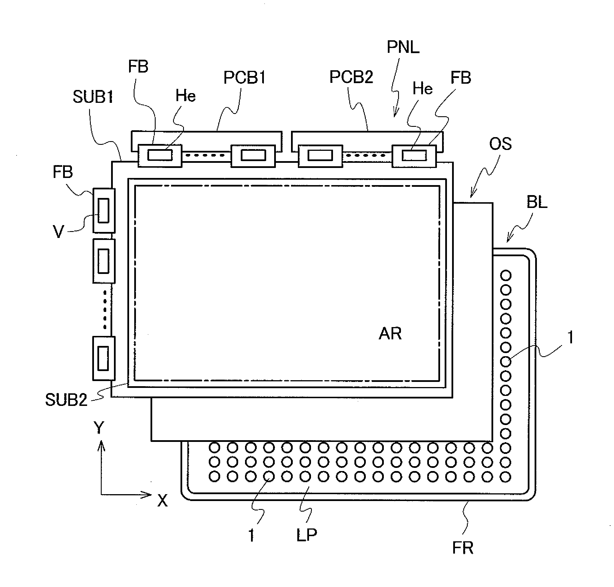
[0032]FIG. 7 is a schematic diagram showing the configuration of a liquid crystal display device to which the invention is applied. A liquid crystal display panel PNL is disposed on the side of a viewer, and on the rear of the liquid crystal display panel PNL, a sheet OS and a backlight BL are disposed in order.

[0033]The liquid crystal display panel PNL is provided with a pair of glass-made substrates SUB1 and SUB2 that are disposed to be parallel to each other, for example. These substrates SUB1 and SUB2 sandwich a liquid crystal material therebetween. On the respective surfaces of the substrates SUB1 and SUB2 facing the liquid crystal material, a plurality of pixels (not shown) arranged in a matrix are formed with the liquid crystal material serving as one configuration component, thereby enabling control over a transmittance of light on a pixel basis. The area formed with the pixels as...


PUM

PropertyMeasurementUnit
colorsaaaaaaaaaa
coloraaaaaaaaaa
color of emissionaaaaaaaaaa

Abstract

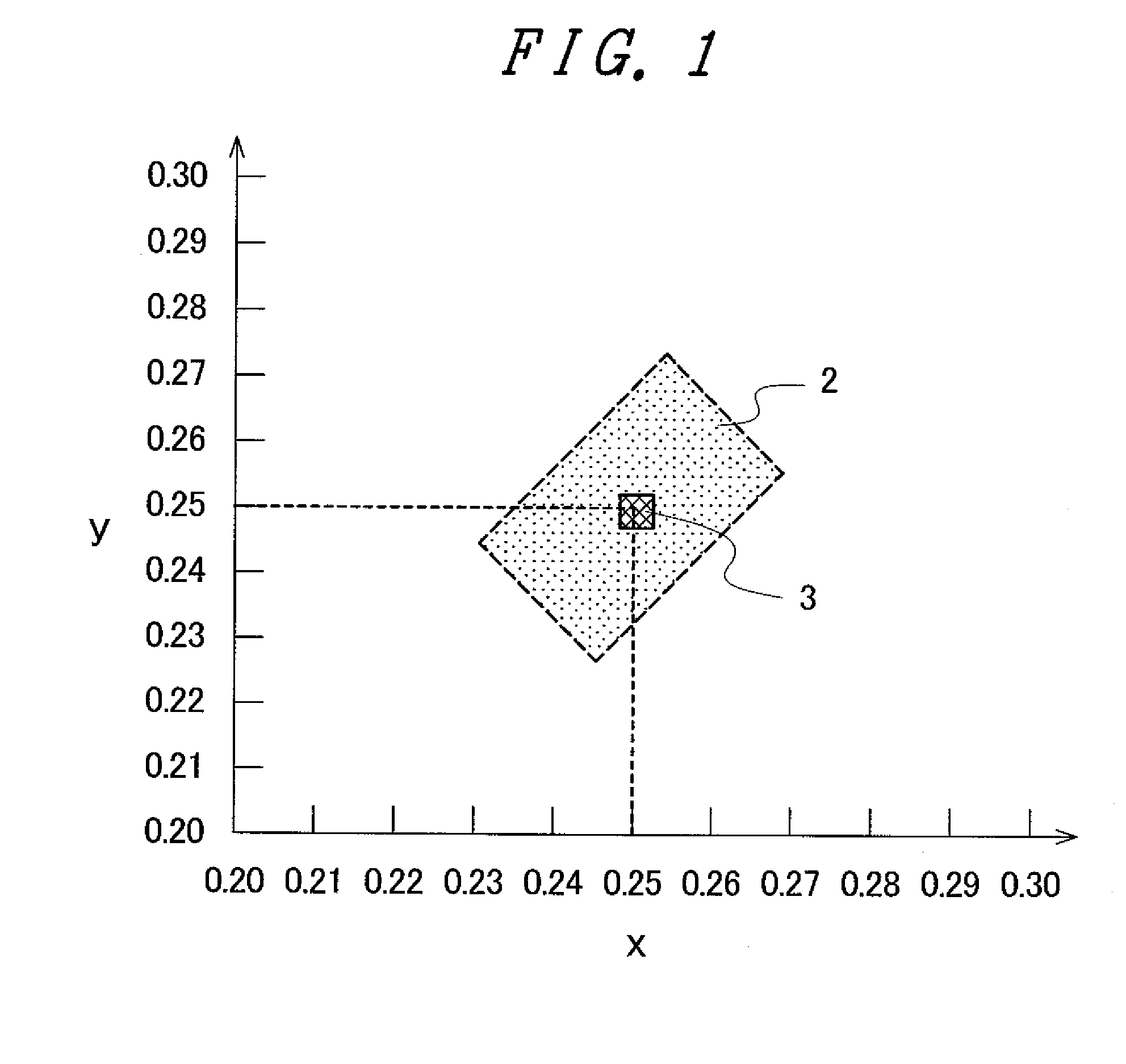
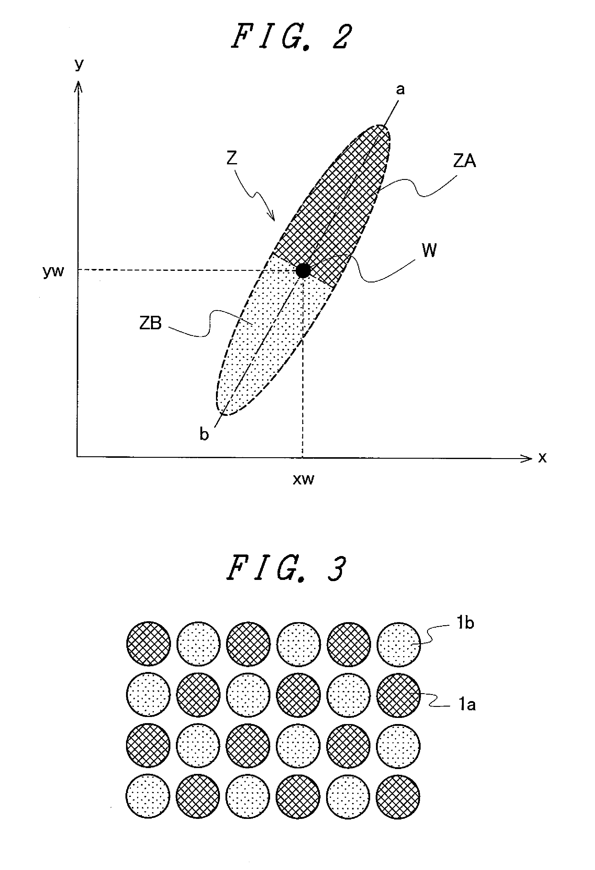
In a liquid crystal display device including a liquid crystal display panel, and a backlight disposed on the rear surface of the liquid crystal display panel, the backlight is provided with a plurality of white light-emitting diodes arranged in a plane opposing the liquid crystal display panel. Based on a chromaticity coordinate value representing a color of emission identified for each of the white light-emitting diodes, the white light-emitting diodes are selectively combined for arrangement in proximity in such a manner that the color of emission as a result of averaging over the white light-emitting diodes (1a, 1b) to be arranged in proximity takes a predetermined value of chromaticity coordinates. Accordingly, the resulting liquid crystal display device can offer, although using the white light-emitting diodes having the problem of impairing the uniformity of the color of emission, higher-quality display images using a backlight with less non-uniformity of color and light emission as a whole, and prevents the increase of the manufacturing cost.

Description

[0001]The present application claims priority from Japanese application JP 2009-015119 filed on Jan. 27, 2009, the content of which is hereby incorporated by reference into this application.BACKGROUND OF THE INVENTION[0002]1. Field of the Invention[0003]The present invention relates to a liquid crystal display device and, more specifically, to a liquid crystal display device using a backlight in which a plurality of white light-emitting diodes are systematically arranged in a planar view.[0004]2. Description of the Related Art[0005]A liquid crystal display device is generally provided with a backlight for illuminating a liquid crystal panel from the rear surface thereof. The backlight can be various types of light emission source, and is mainly exemplified by a fluorescent tube including a cold cathode tube, an external electrode fluorescent lamp, and others, a planar light source including an electroluminescent light source, and a point light source including a light-emitting diode...

Claims


Application Information

Patent Timeline
Patent Type & Authority Patents(United States)
IPC IPC(8): G02F1/1335
CPCG02F1/133603G02F1/133609G02F2001/133613G02F1/133613
Inventor IMAJO, IKUKOOKE, RYUTAROYAMAZAKI, SACHIKOBABA, MASASHI
Owner JAPAN DISPLAY INC
Learn More