Apparatus for high-accuracy fiber counting in air

a technology of fiber counting and air, applied in the direction of instruments, porous material analysis, measurement devices, etc., can solve the problems of their usefulness, and achieve the effect of reducing the inhalation hazard of airborne fibers, minimal attention or intervention

Active Publication Date: 2010-11-09
MSP
View PDF5 Cites 5 Cited by
  • Summary
  • Abstract
  • Description
  • Claims
  • Application Information

AI Technical Summary

Benefits of technology

[0004]The output of the photo detector is provided to circuitry that provides a pulse train that indicates the concentration of fibers carried in the gas flowing in the passage way. The apparatus disclosed permits counting the fibers accurately and reliably to determine the concentration of fibers in an environment in which workers may be present. Upon detecting a potentially harmful level of airborne fibers, the apparatus may provide a visual or audible alarm to alert workers that respiratory protection devices, such as face masks, may be needed in order to reduce the inhalation hazard of airborne fibers. The apparatus disclosed is capable of operating automatically with minimal attention or intervention by a user.

Problems solved by technology

While automatic fiber counting devices have been developed (U.S. Pat. No. 4,940,327), there are major shortcomings in the instrument design that have limited their usefulness in the past.

Method used


Image

  • Apparatus for high-accuracy fiber counting in air
  • Apparatus for high-accuracy fiber counting in air
  • Apparatus for high-accuracy fiber counting in air

Examples


Embodiment Construction

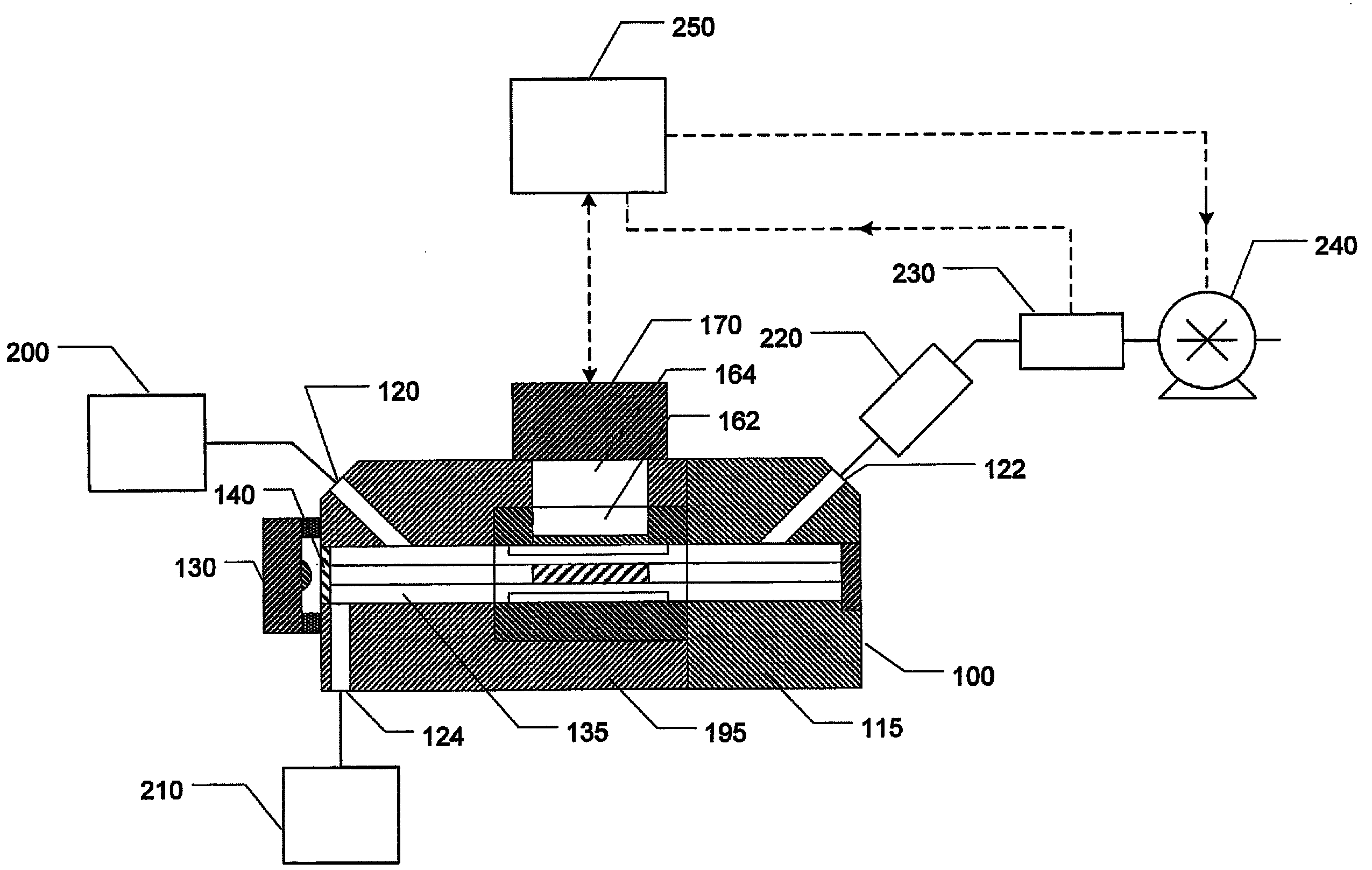
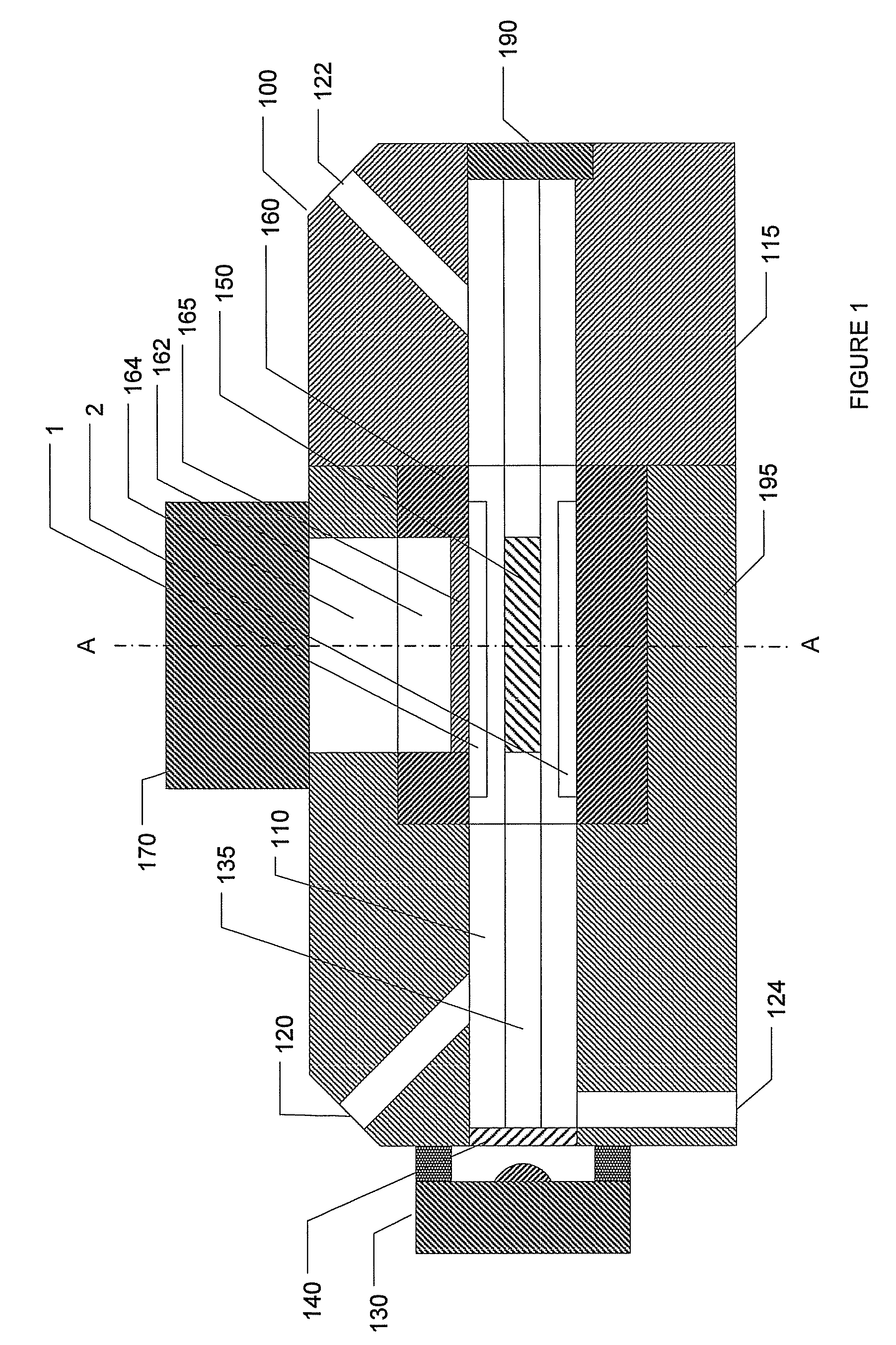
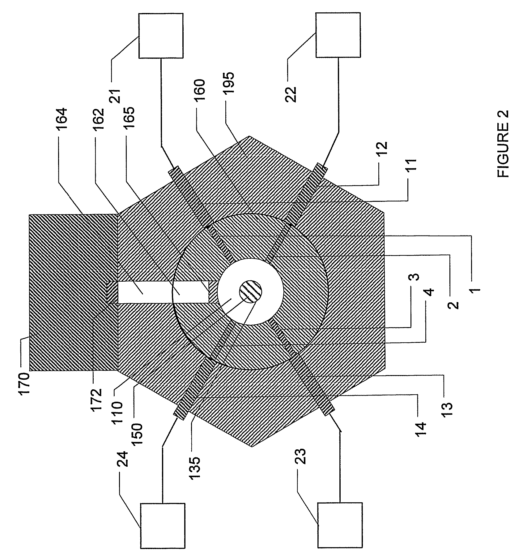
[0011]FIG. 1 is a longitudinal sectional view of a fiber detecting module 100 of the present disclosure showing a tubular, cylindrical flow passageway, 110, through which an air (gas) flow carrying suspended fibers passes. Fiber detecting module 100 is provided with an inlet 120 for the sample air flow from a source 200 (FIG. 6) to enter, and an outlet 122 for the air flow to exit. A light source, typically a solid-state laser light source 130 mounted on one end of module 100 projects a beam of light 135 into the cylindrical flow passageway 110. A lens 140 in the path of the laser beam 135 reduces the angular divergence of the beam so that a nearly parallel beam of laser light is projected through the cylindrical flow passageway 110 for fiber detection. Fiber detection occurs within a detection zone 150 in the flow pasageway 110. The detection zone 150 is a portion of the flow passageway formed in a separate cylindrical piece 160, which is a removable sub-assembly inserted into a bo...


PUM

PropertyMeasurementUnit
diameteraaaaaaaaaa
frequencyaaaaaaaaaa
timeaaaaaaaaaa

Abstract

The present disclosure has an apparatus for detecting fibers in a gas flowing along a passageway. A laser beam is provided at one end of the passageway and the beam is directed along a length of the passageway through which the gas flows. An electrode system, as disclosed, a quadrupole electrode system is mounted along the passageway to cause fibers carried in the gas to oscillate in a detection zone. A photo detector is positioned laterally of the passageway and detects light scattered by the oscillating fibers and projected through an opening in the passageway to provide an output signal that is a function of the light scattered by the fibers in the detection zone.

Description

[0001]This application refers to and claims priority on U.S. Provisional Patent application Ser. No. 61 / 103,124, filed Oct. 6, 2008, and the content of which is incorporated by reference in its entirety.BACKGROUND OF THE DISCLOSURE[0002]The present disclosure relates to a method and apparatus for counting fibers suspended in air or other gases in order to detect the presence of fibrous material, such as asbestos fiber, other natural and man-made fibers, and the like that may be harmful or injurious to health when inhaled into the lung. While automatic fiber counting devices have been developed (U.S. Pat. No. 4,940,327), there are major shortcomings in the instrument design that have limited their usefulness in the past. The present apparatus is aimed at overcoming the shortcomings of the previous fiber counting devices in order to have a reliable, high accuracy modern instrument for automatic fiber counting in the work place environment.SUMMARY OF THE DISCLOSURE[0003]The present dis...

Claims


Application Information

Patent Timeline
Patent Type & Authority Patents(United States)
IPC IPC(8): G01N21/00
CPCG01N15/06G01N21/53G01N2015/0693G01N2021/4759G01N2021/513
Inventor LIU, BENJAMIN Y. H.DICK, WILLIAM D.ROMAY, FRANCISCO J.BATTISTA, MARK J.LILIENFELD, PEDRO
Owner MSP
Why Eureka
Try Eureka