Projection objective of a microlithographic projection exposure apparatus

a technology of exposure apparatus and projection objective, which is applied in the direction of printers, instruments, photomechanical treatment, etc., can solve the problems of image errors, uniform heating of optical elements, and difficult correction of image errors which are not rotationally symmetric, so as to reduce rotationally symmetric image errors and simple design

Inactive Publication Date: 2010-11-09
CARL ZEISS SMT GMBH
View PDF58 Cites 55 Cited by
  • Summary
  • Abstract
  • Description
  • Claims
  • Application Information

AI Technical Summary

Benefits of technology

[0022]It is an object of the present invention to provide a projection objective of a microlithographic projection exposure apparatus, which has a manipulator for reducing rotationally asymmetric image errors. More particularly, the manipulator shall have a simple design and shall make it possible to correct a large variety of rotationally asymmetric field or pupil related image errors.

Problems solved by technology

Correction of those image errors which are not rotationally symmetric is more difficult.
Such image errors occur, for example, because lenses and other optical elements heat up rotationally asymmetrically.
One image error of this type is astigmatism, which may also be encountered for the field point lying on the optical axis.
The slit-shaped illumination field causes a non-uniform heating of the optical elements, and this induces image errors which often have a twofold symmetry.
However, image errors with other symmetries, for example threefold or fivefold, or image errors characterized by completely asymmetric wavefront deformations are frequently observed in projection objectives.
Completely asymmetric image errors are often caused by material defects which are statistically distributed over the optical elements contained in the projection objective.
This is disadvantageous because it is thereby very difficult to correct a particular wavefront deformation, which is determined by measurements or simulation, and has been generated by the other elements of the projection objective.
A disadvantage with this known manipulator, however, is that only the fluid pressure is available as a variable parameter.
Since always a plurality of optical surfaces are simultaneously deformed by changing the pressure of the liquid, it is difficult to widely correct a certain (measured) wavefront deformation without introducing a plurality of other deformations.
With these known liquid lenses the deformation is always rotationally symmetric, and hence they are not suitable for correcting rotationally asymmetric image errors.

Method used


Image

  • Projection objective of a microlithographic projection exposure apparatus
  • Projection objective of a microlithographic projection exposure apparatus
  • Projection objective of a microlithographic projection exposure apparatus

Examples


Embodiment Construction

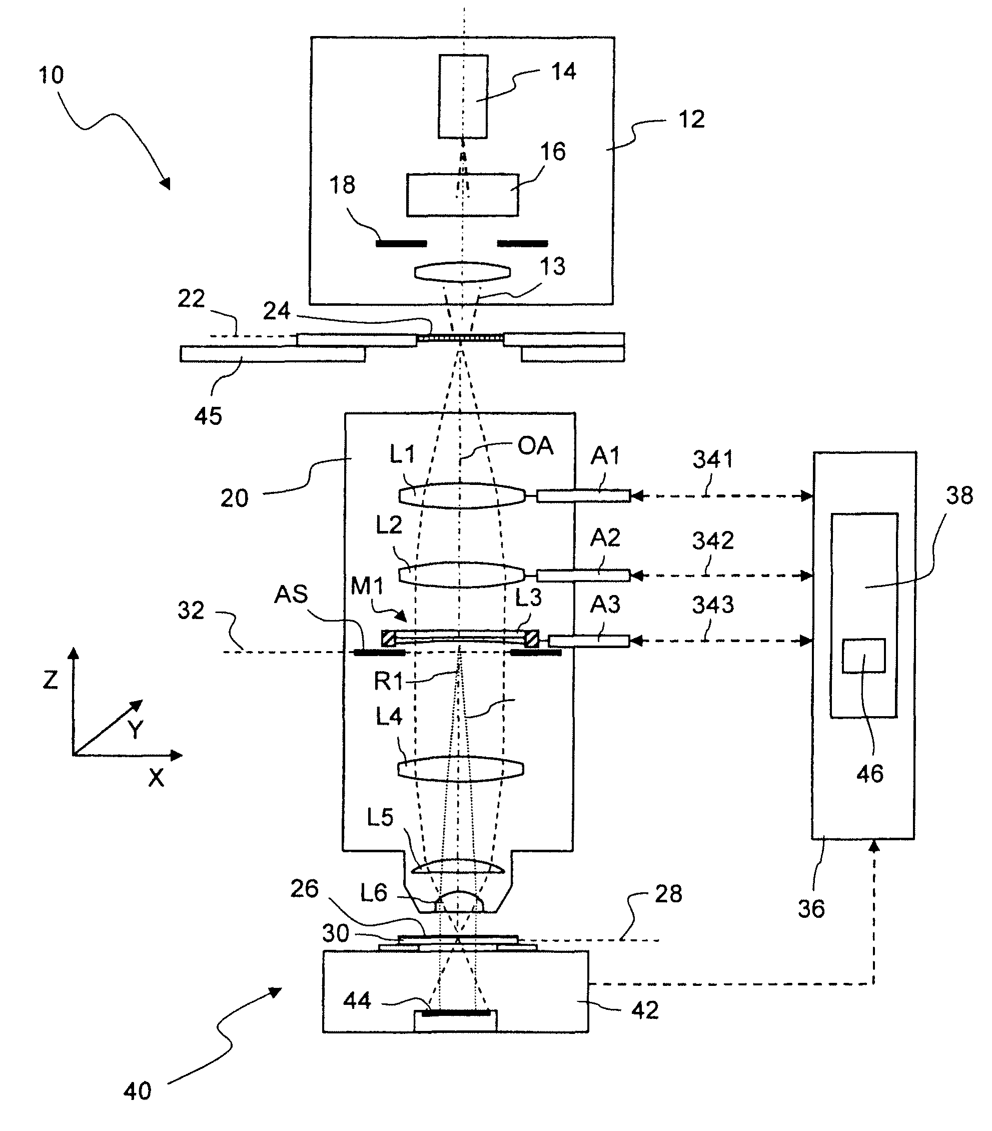
[0080]FIG. 1 shows, in a highly schematized meridian section, a microlithographic projection exposure apparatus 10 in a projection mode. The projection exposure apparatus 10 comprises an illuminating system 12 for generating projection light 13. The illumination system 12 contains a light source 14, illumination optics 16 and a field stop 18. The illumination optics 16 make it possible to set different illumination angle distributions.

[0081]The projection exposure apparatus 10 further comprises a projection objective 20, which contains an aperture stop AS and a plurality of optical elements. For the sake of clarity, only a few optical elements are schematically illustrated in FIG. 1 and denoted by L1 to L6. The projection objective 20 projects a reduced image of a mask 24, which is arranged in an object plane 22 of the projection objective 20, onto a photosensitive layer 26 which is arranged in an image plane 28 of the projection objective 20. The photosensitive layer 26 may be form...


PUM


Abstract

A projection objective of a microlithographic projection exposure apparatus comprises a manipulator for reducing rotationally asymmetric image errors. The manipulator in turn contains a lens, an optical element and an interspace formed between the lens and the optical element, which can be filled with a liquid. At least one actuator acting exclusively on the lens is furthermore provided, which can generate a rotationally asymmetric deformation of the lens.

Description

CROSS-REFERENCE TO RELATED APPLICATIONS[0001]This application is a continuation application of and claims priority to PCT International Application No. PCT / EP2006 / 007273, filed on Jul. 24, 2006, which claims priority to U.S. Provisional Application Ser. No. 60 / 702,137, filed Jul. 25, 2005.BACKGROUND OF THE INVENTION[0002]1. Field of the Invention[0003]The invention relates to projection objectives of microlithographic projection exposure apparatus. Such apparatus are used for the production of large-scale integrated circuits and other microstructured components. The invention relates in particular to projection objectives comprising a manipulator for reducing rotationally asymmetric image errors.[0004]2. Description of Related Art[0005]Microlithography (also called photolithography or simply lithography) is a technology for the fabrication of integrated circuits, liquid crystal displays and other microstructured devices. The process of microlithography, in conjunction with the proce...

Claims


Application Information

Patent Timeline
Patent Type & Authority Patents(United States)
IPC IPC(8): G02B1/06G02B3/02G02B27/02
CPCG02B3/14G02B27/0068G03F7/70266G03F7/70825
Inventor CONRADI, OLAFBLEIDISTEL, SASCHAHAUF, MARKUSHUMMEL, WOLFGANGKAZI, ARIFSCHWAER, BAERBELWEBER, JOCHENHOLDERER, HUBERTTAYEBATI, PAYAMBITTNER, BORIS
Owner CARL ZEISS SMT GMBH
Why Eureka
Try Eureka