
Riser assembly for use with fluid sprinkler

Active Publication Date: 2010-11-16
COLLINS WADE E
View PDF12 Cites 13 Cited by
  • Summary
  • Abstract
  • Description
  • Claims
  • Application Information

AI Technical Summary

Benefits of technology

[0006]There accordingly exists a need for a riser assembly useable even with high output directional sprinklers that facilitates rapid, efficient, yet sturdy and easily modifiable connection of the riser assembly to a pressurized fluid source and that does not require a concrete pier or even burial of a majority of the riser assembly in the ground. A need also exists for an adjustably weighted riser assembly that accomplishes the foregoing purposes and can be easily and efficiently installed, maintained, removed and reinstalled with minimal use of tools and without damage to the riser assembly and any associated signal carrier, signal processor or means for controlling expulsion of fluid through the sprinkler. The assembly of the present invention addresses these needs.
[0015]Another object of this invention is to provide an assembly in accordance with the preceding objects which will conform to conventional forms of manufacture, be of comparatively simple construction and easy to use so as to provide an invention that will be economically feasible, durable and relatively free of trouble in use and operation.

Problems solved by technology

The installation, maintenance, removal and transport of a riser assembly can present a number of challenges.
Particularly in the case of riser assemblies used with high output directional sprinklers, a first set of challenges arises from the fact that expulsion of fluid through the sprinkler can exert significant and potentially destabilizing forces upon the riser assembly.
This challenge is compounded where such forces may be exerted from varying angular, or lateral directions as, for example, in the case of a riser assembly used with a powerful rotary sprinkler.
Another set of challenges arises from temperature variations, precipitation and other environmental conditions encountered in the often rugged outdoor settings where a riser assembly is used.
These environmental conditions can pose a challenge not only to the riser assembly itself but additionally to functional elements operatively connectable with the riser assembly and, particularly, to wires and other signal carriers, signal processors and control valves.
Such attempts to stabilize riser assemblies have typically resulted in assemblies that are: (1) complicated, difficult, expensive and time consuming to install and maintain, and (2) complicated, difficult, expensive or even impossible to remove, transport and reinstall.
Advantages of feedlot irrigation include minimization of airborne dust which can produce nose, respiratory, skin and eye problems.

Method used


Image

  • Riser assembly for use with fluid sprinkler
  • Riser assembly for use with fluid sprinkler
  • Riser assembly for use with fluid sprinkler

Examples


Embodiment Construction

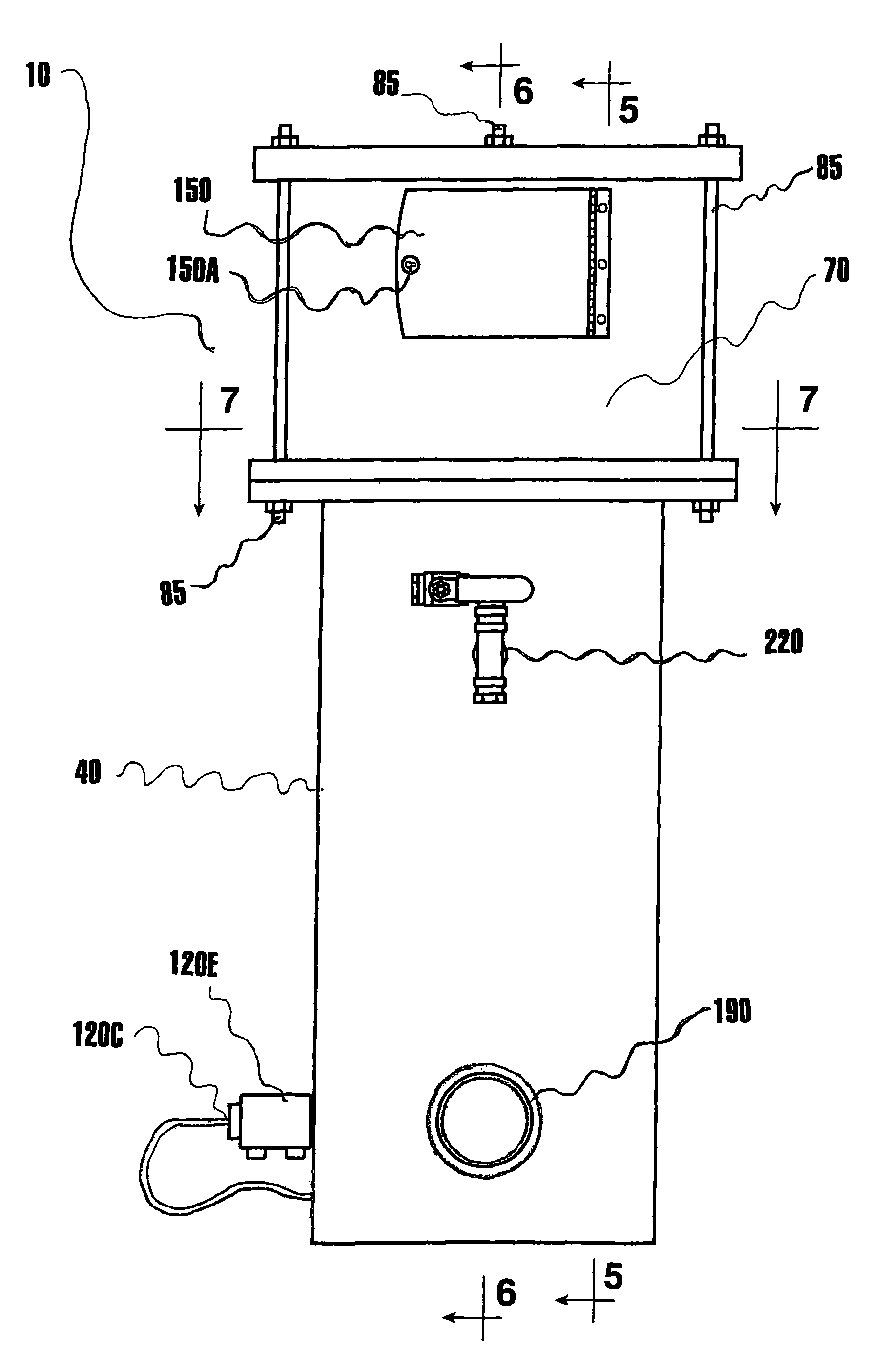
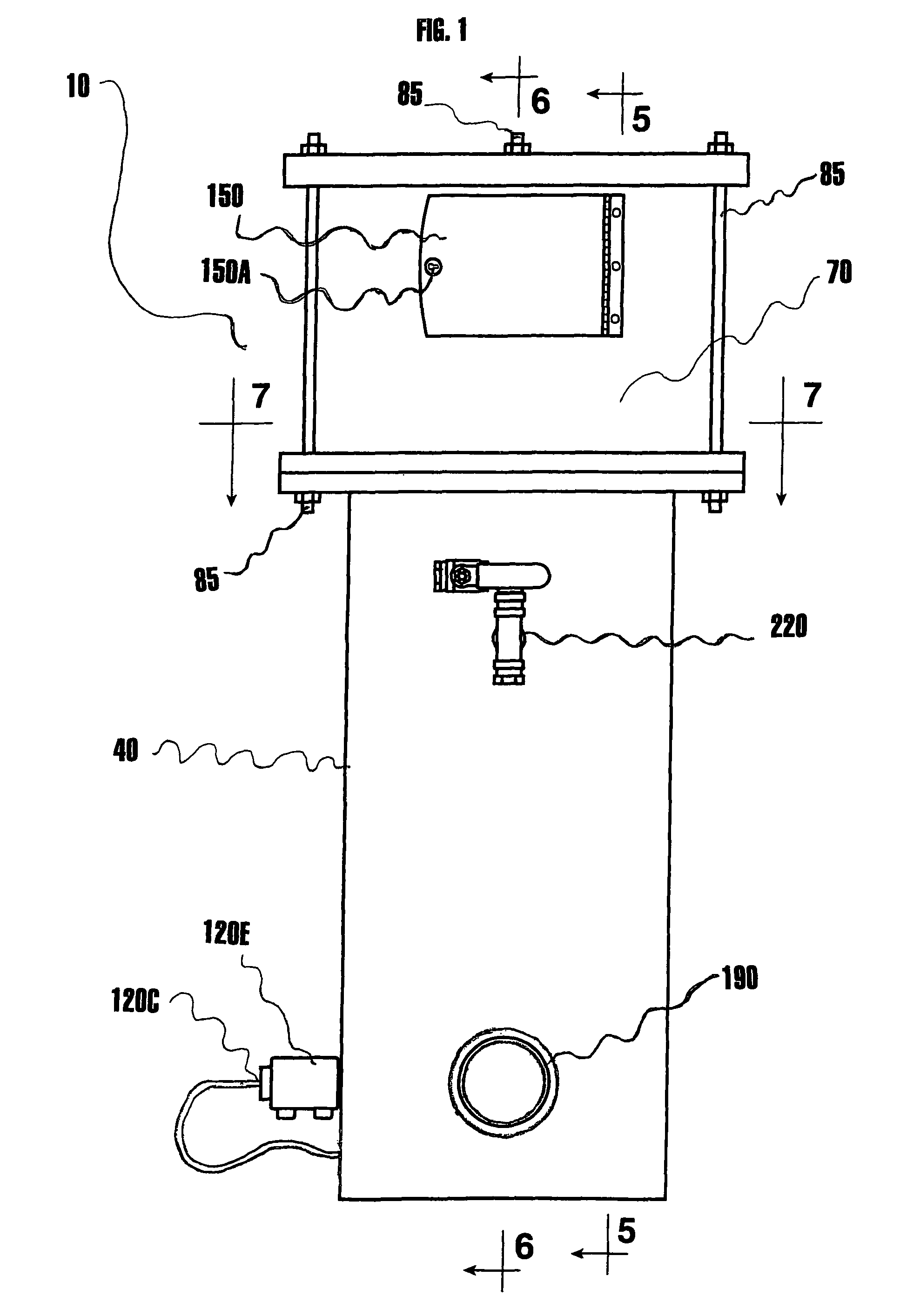
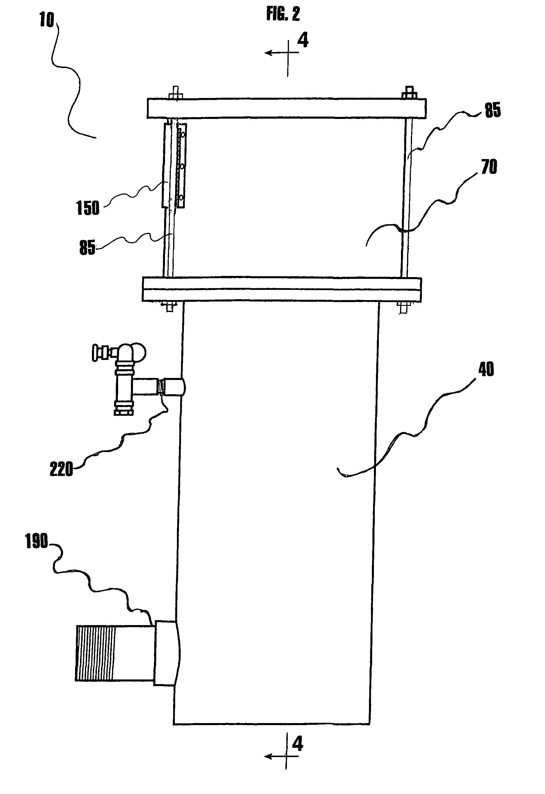
[0030]FIGS. 1 through 3 illustrate a preferred embodiment of a riser assembly 10. The riser assembly 10 is designed for use with a fluid dispenser, the fluid dispenser being preferably a sprinkler illustrated generally as item 20 in FIG. 8 and, particularly, a sprinkler for spraying pressurized fluids with an associated control valve 30 (FIG. 9) for selectively controlling fluid expelled through the sprinkler 20.

[0031]With attention directed principally to FIGS. 1 through 7, it is seen that a preferred embodiment of the riser assembly 10 includes: (1) a container 40 having a side wall 40A, a top 40B and a bottom 40C, the container 40 partially circumscribing a reservoir 50 (FIGS. 4, 5, 6 and 9) for containing a pressurized fluid 60, the container 40 having a fluid inlet 40D and a fluid outlet 40E (FIG. 6) disposed therethrough; (2) a cover 70 connectable by a plurality of fasteners 85 to the top 40B of the container 40, the cover 70 having an aperture 80 (FIG. 6) for containing a sp...


PUM


Abstract

The invention is riser assembly for use with a fluid dispenser particularly a sprinkler. The assembly includes: (1) a container partially circumscribing a reservoir for containing a pressurized fluid, the container having a fluid inlet and a fluid outlet disposed therethrough, and (2) a conduit circumscribing a channel occupiable by a signal carrier, the conduit including an intermediate conduit portion disposed within the reservoir, a first conduit portion disposed through the container to a signal carrier entry area outside the container and a second conduit portion disposed through the container to a signal carrier exit area outside the container. The assembly may include a cover connectable to the container, the cover having an aperture for containing the fluid dispenser disposed therethrough, a protective cavity being formed between the cover and the container.

Description

TECHNICAL FIELD[0001]The invention relates to a riser assembly for use with a fluid dispenser. More specifically, the invention relates to an adjustably weighted riser assembly for use with a fluid dispensing sprinkler, the riser assembly including a reservoir for containing a pressurized fluid and a conduit circumscribed channel occupiable by a signal carrier, the conduit having a fluid excluding intermediate portion disposed within the reservoir.SUMMARY OF THE INVENTION[0002]Processes for conveying fluid from a pressurized fluid source through a fluid dispensing sprinkler are known. In a typical practice, fluid pressurized by a pump is conveyed from a supply pipe through a riser assembly and expelled through a sprinkler. Various means for controlling expulsion of fluid through a sprinkler have been utilized. These means for controlling fluid expulsion include associating a control valve with the sprinkler, associating a control valve with the riser assembly or associating a contro...

Claims


Application Information

Patent Timeline
IPC IPC(8): B05B15/06
CPCB05B12/00B05B15/061B05B3/04B05B15/10B05B15/62B05B15/74
Inventor COLLINS, WADE E.
Owner COLLINS WADE E
Learn More