Head protecting airbag system

a technology for protecting airbags and head, which is applied in the direction of pedestrian/occupant safety arrangements, vehicular safety arrangments, vehicle components, etc., and can solve the problem of affecting the direction in which the airbag is deployed

Active Publication Date: 2010-11-16
TOYOTA JIDOSHA KK +1
View PDF19 Cites 13 Cited by
  • Summary
  • Abstract
  • Description
  • Claims
  • Application Information

AI Technical Summary

Benefits of technology

[0008]The present invention provides a head protecting airbag system having an airbag for deploying an inflation section of the airbag between an occupant's head and a side vehicle body, while preventing a bottom end of the airbag from protruding over a bottom edge of a side window opening.
[0010]When at least one of a side collision and a rollover occurs to the vehicle, the inflator is activated to supply gas into the airbag folded-up in the vehicle height direction and stored along the roof side rail section of the vehicle. This allows the airbag to be deployed downward along the side vehicle body in the passenger compartment. The airbag includes the gas supply path connected to the inflator and the inflation section connected to the gas supply path to protect an occupant's head. The occupant's head is thus protected by the inflation section.
[0011]According to the first aspect of the invention, the horizontal cell is provided in the vehicle longitudinal direction below the inflation section constituted by plural cells and deployed toward the passenger compartment with respect to the side window opening. The horizontal cell is deployed to an area of the passenger compartment below the side window opening after the inflation section is deployed. In other words, with the inflation section, designed to protect the head of the occupant, deploying downward along the side of the vehicle body in the passenger compartment, the horizontal cell deploys in the passenger compartment to an area below the side window opening. This prevents the horizontal cell from being deployed in the process of deploying the inflation section, and therefore, prevents the horizontal cell deployed from protruding over a bottom edge of the side window opening.
[0012]As described above, the invention allows the airbag to be deployed between the head of the occupant and the side of the vehicle body without protruding over the bottom edge of the side window opening in the process of deploying the airbag.

Problems solved by technology

However, the direction in which the airbag is deployed tends to be affected by the manner in which the airbag is folded.

Method used


Image

  • Head protecting airbag system
  • Head protecting airbag system
  • Head protecting airbag system

Examples


Embodiment Construction

[0019]A head protecting airbag system according to one embodiment of the invention will be described below with reference to FIGS. 1 to 5.

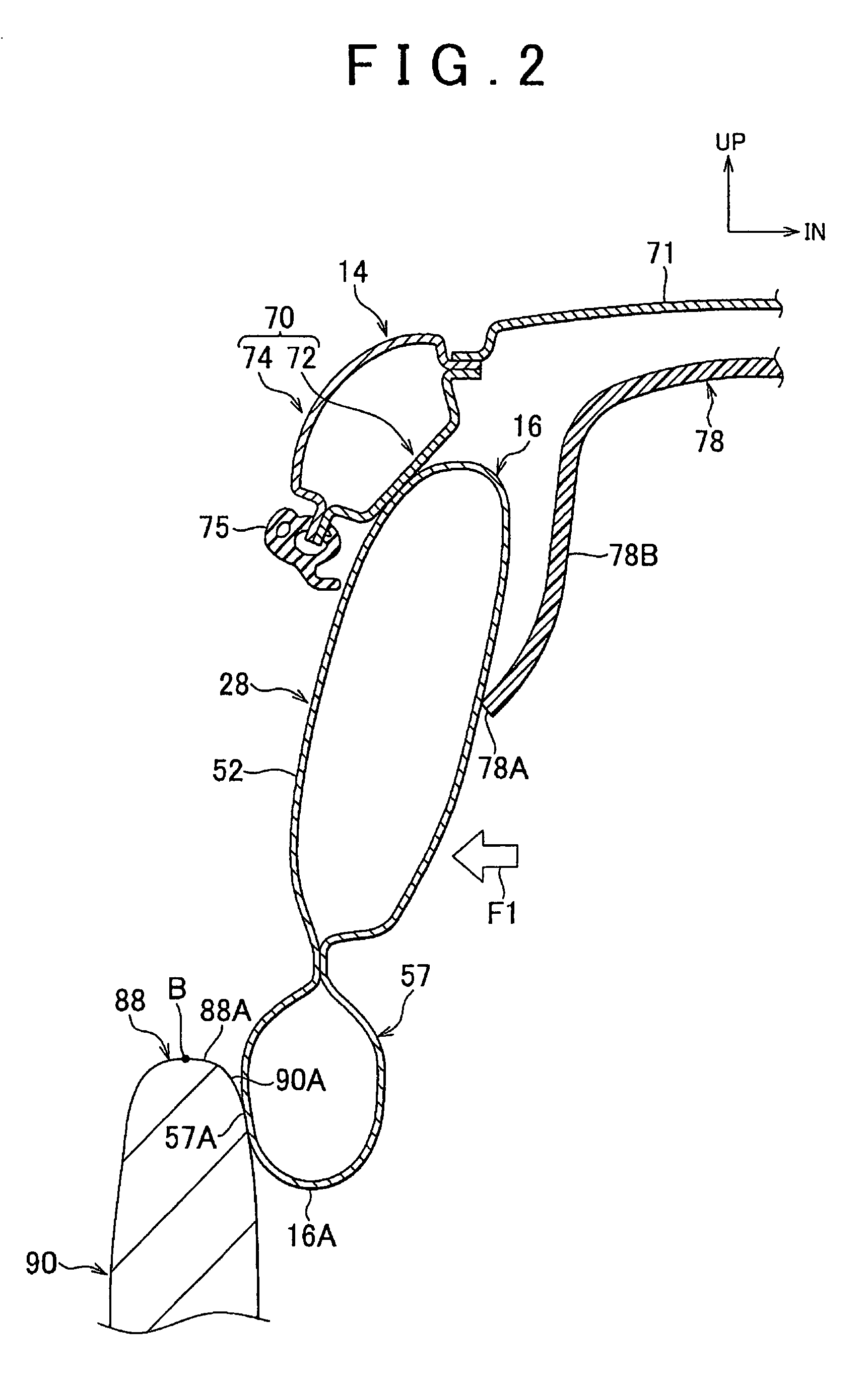
[0020]In FIGS. 1 to 3, the arrow FR and the arrow UP indicate forward direction and upward direction of the vehicle, respectively, while the arrow IN indicates inward direction with respect to the vehicle width.

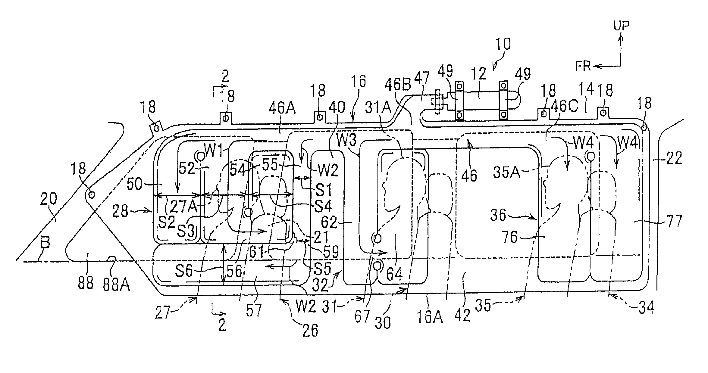
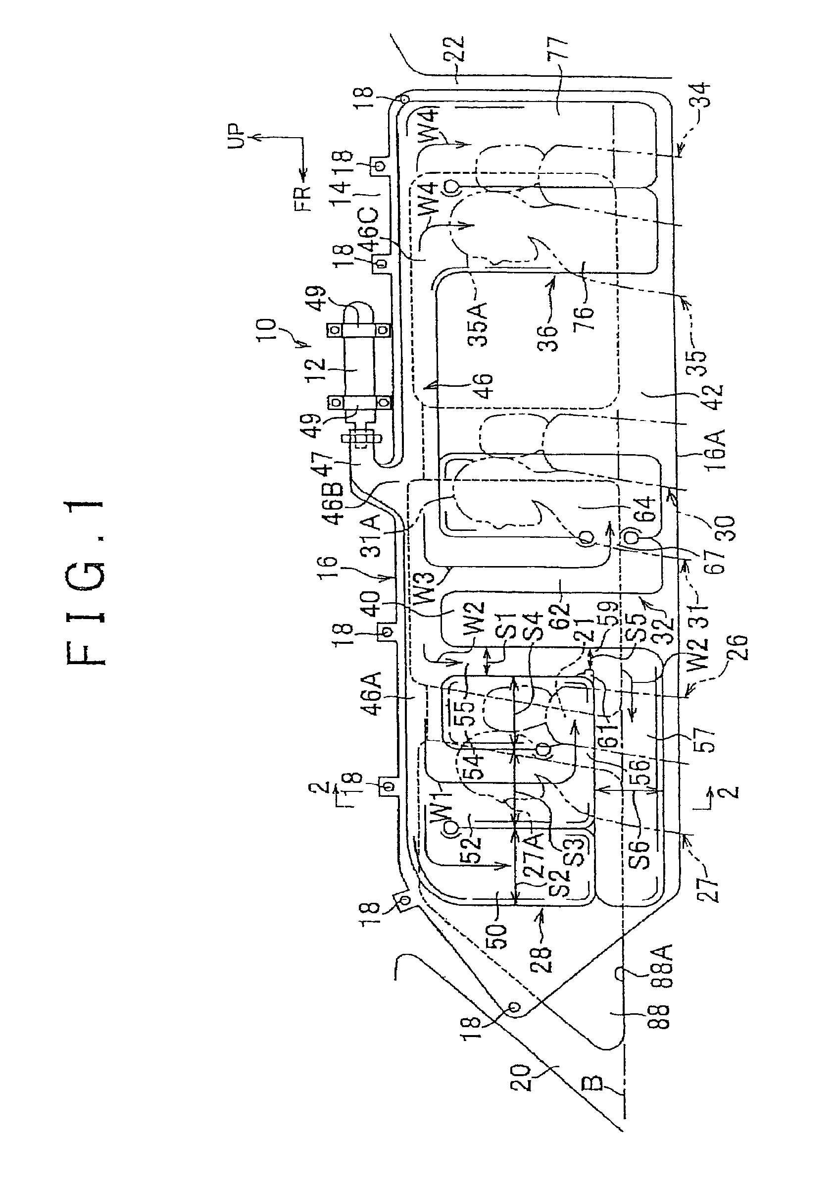
[0021]FIG. 1 is a side view of a head protecting airbag system 10 according to the embodiment, in which the airbag 16 is deployed.

[0022]As shown in FIG. 1, the head protecting airbag system 10 includes a cylindrical inflator 12 and the airbag 16. The inflator 12 injects gas from its gas injecting portion when the inflator 12 is activated. The gas injecting portion of the inflator 12 connects to the airbag 16. The airbag 16 is folded in the vehicle height direction into a long rectangle that extends in the vehicle longitudinal direction, such that the folded airbag 16 is stored along a roof side rail section 14.

[0023]The inflator 12 is activ...


PUM


Abstract

A vertical cell is formed in a forward inflation section of an airbag. The vertical cell extends in a vehicle height direction at the rear of a pillar, and communicates through a bottom end of the vertical cell with a horizontal cell. When the inflation section is deployed, the folded horizontal cell or the lower side part of the airbag is pulled back toward the passenger compartment with respect to the side window opening. Accordingly, the horizontal cell deploys to an area below a bottom edge of the side window opening or a beltline in the passenger compartment on the inner side of a front side door.

Description

INCORPORATION BY REFERENCE[0001]The disclosure of Japanese Patent Application No. 2006-236020 filed on Aug. 31, 2006 including the specification, drawings and abstract is incorporated herein by reference in its entirety.BACKGROUND OF THE INVENTION[0002]1. Field of the Invention[0003]The present invention relates to a head protecting airbag system that deploys an airbag downward along the side of a vehicle body in a passenger compartment when the vehicle is involved in either a side collision or a rollover. In particular, the present invention relates to a head protecting airbag system that deploys an inflation section between an occupant's head and the vehicle body.[0004]2. Description of the Related Art[0005]In the recent trends, a head protecting airbag system is mounted to vehicles as a supplemental restraint system. The head protection airbag system has a curtain airbag that is deployed downward from a roof side rail when the vehicle is involved in a side collision or rollover. ...

Claims


Application Information

Patent Timeline
Patent Type & Authority Patents(United States)
IPC IPC(8): B60R21/16B60R21/20B60R21/213B60R21/232
CPCB60R21/232B60R13/0212B60R21/213
Inventor MITSUO, TETSUNARUI, AKIHIKONOGAMI, MITSUO
Owner TOYOTA JIDOSHA KK
Why Eureka
Try Eureka