Method and structures of a miniaturized line lamp

a line lamp and miniaturization technology, applied in the direction of lighting and heating equipment, semiconductor devices for light sources, lighting support devices, etc., can solve the problems of inability to effectively control the problem of miniaturization and space taking, and the prior art cannot be really implemented in a large quantity in living, so as to achieve the effect of decreasing the size of the line lamp

Inactive Publication Date: 2011-09-22
SHAO YI SHIANG
View PDF8 Cites 27 Cited by
  • Summary
  • Abstract
  • Description
  • Claims
  • Application Information

AI Technical Summary

Benefits of technology

The primary object of the present invention is to provide a method and structures of a miniaturized line lamp which provide for decreasing a size of a line lamp without taking up space, allowing an application to be wider.
In the present invention, each across corner of the LED at a relative electrode is formed respectively with a notch area free of electrode, whereas the other end is a no-notch area of electrode. The LED is transversally located between two metal wires, allowing the two metal wires to be located at two sides of the LED, free of electrode, thereby forming a state of clipping. On the other hand, the two no-notch area of electrode can be in contact with the two metal wires respectively to form a loop. Therefore, the LED can be located on a same plane of the metal wires, which reduces a width of the line lamp and avoids that the entire line lamp is protruded by serially connecting the LEDs, thereby achieving a small size to better comply with a requirement of miniaturizing the line lamp and maintaining completeness of the wires.

Problems solved by technology

However, as a conventional serial connection method is taken, meaning that the thin metallic wire is serially connected by welding underneath the LEDs, the LEDs will be protruded with a larger size, i.e., larger or higher than a cross section of the thin metal wire (including less than 2 mm of insulative rubber); in addition, a result of serially connecting an entire string of the line lamp is that the LEDs are protruded on a plane of the metal wire and the size is still large, thus it is unable to effectively control the issues of miniaturization and space taking.
Moreover, the wire assembly which is formed by the serial connection cannot be provided with completeness and the space of collection is large and inconvenient that the requirement of miniaturization cannot be satisfied; therefore, the prior art cannot be really implemented in a large quantity in living, such as clothing, traffic or a military activity.

Method used


Image

  • Method and structures of a miniaturized line lamp
  • Method and structures of a miniaturized line lamp
  • Method and structures of a miniaturized line lamp

Examples


Embodiment Construction

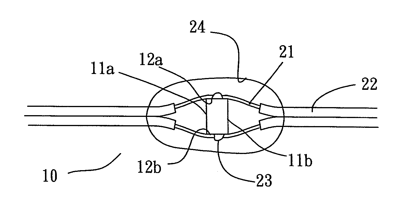
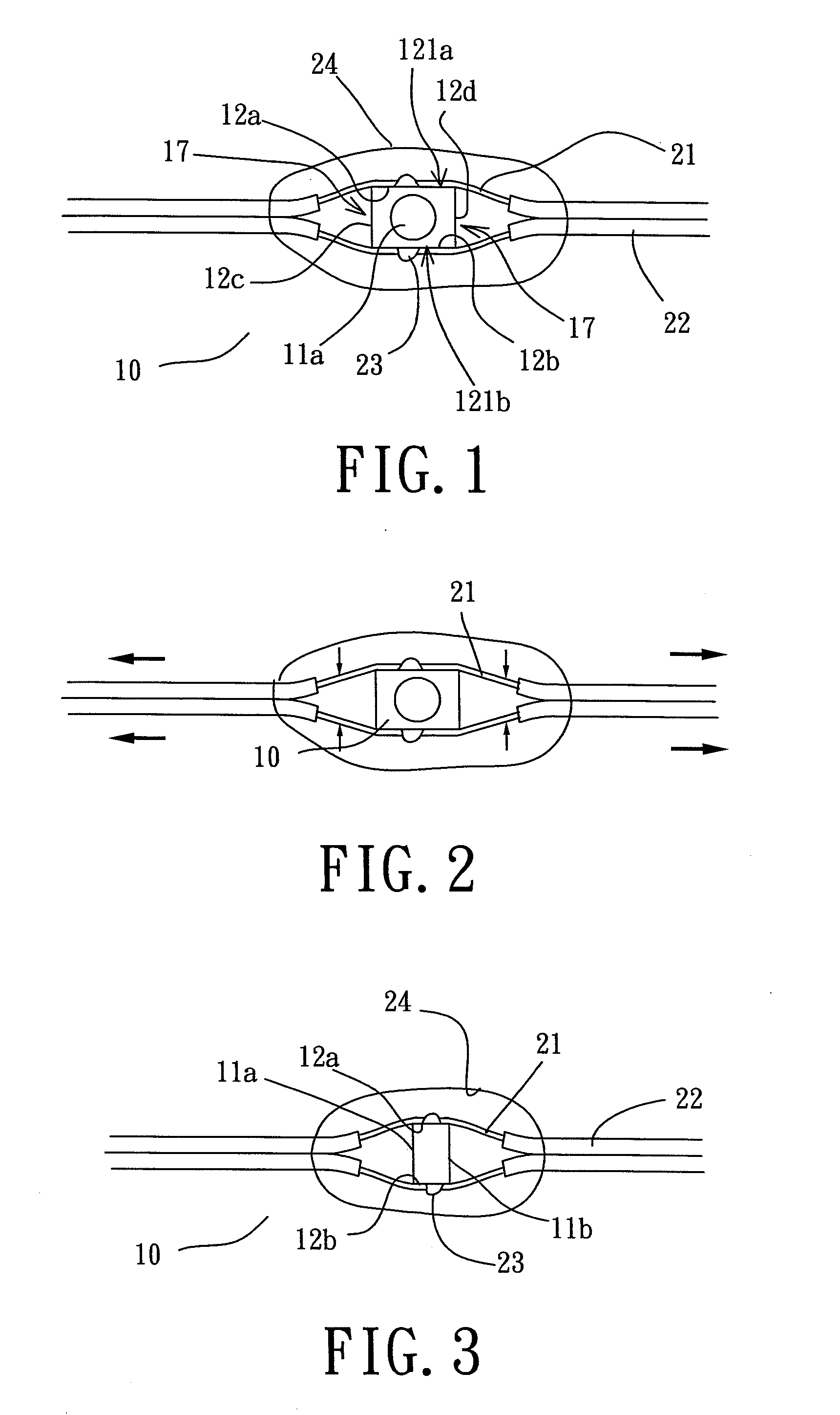
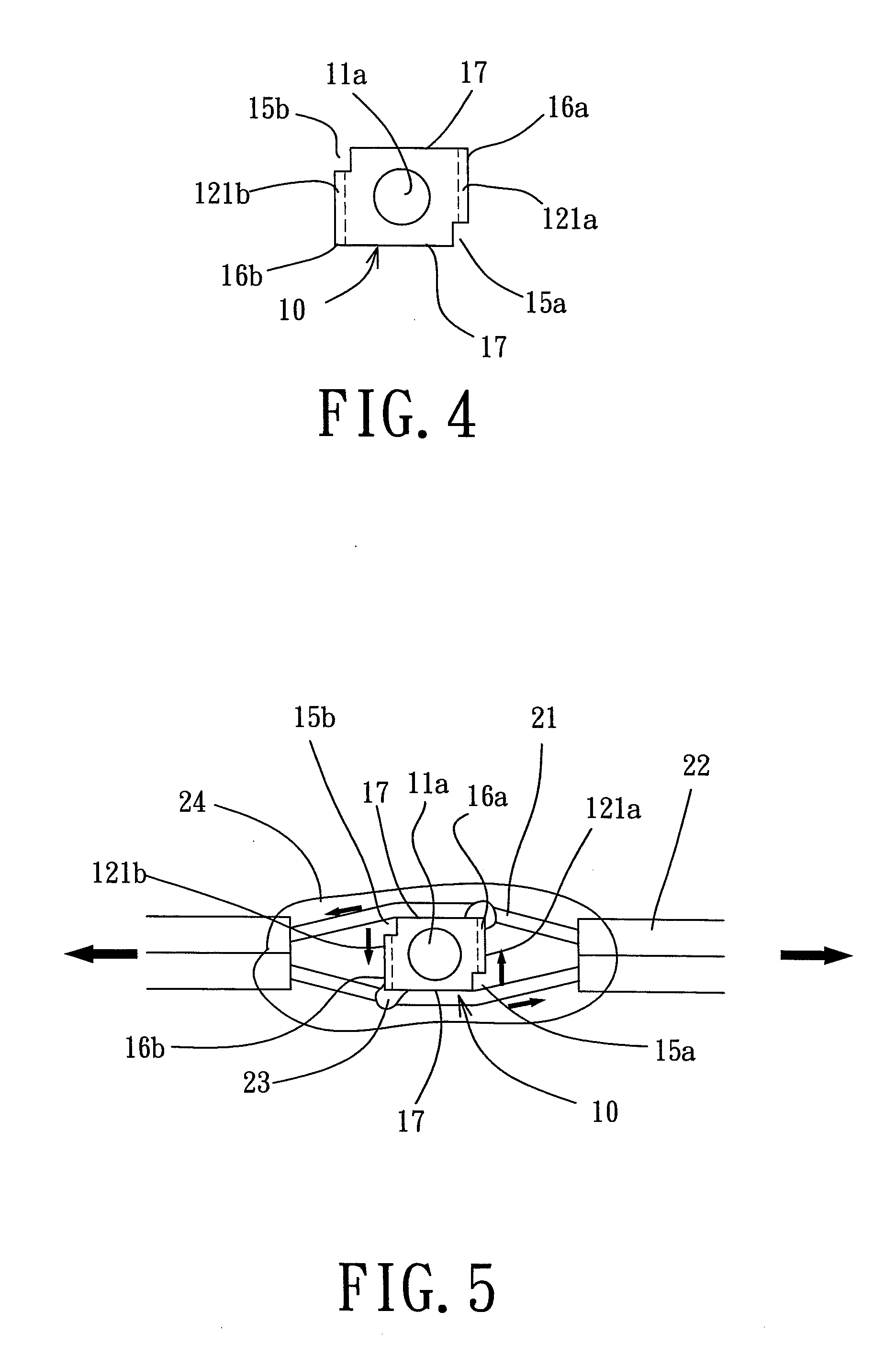
Referring to FIG. 1, for a method of basically miniaturizing a line lamp and steadily holding an LED according to the present invention, a thin electric wire is deployed with at least one LED 10, whereas between a section of two exposed metal wires 21 of the thin electric wire is at least one LED 10 which includes two opposite illumination parts 11a, 11b and non-illumination parts 12a, 12b, 12c, 12d at four sides. On the other hand, positive and negative electrodes 121a, 121b of the LED 10 are positioned at the no-illumination parts 12a, 12b at shorter sides, whereas the two longer sides are the non-illumination parts 12c, 12d at no-electrode positions 17. The two metal wires 21, whereas, are attached on the no-illumination parts 12a, 12b at the positive and negative electrodes 121a, 121b to clip the LED 10 in-between, forming connection at solder joints 23 by an SMT (Surface Mounting Technology) or spot welding.

As two metal wires 21 are crossed over at two opposite positions of the...


PUM


Abstract

The present invention discloses a method and structures of a miniaturized line lamp. Metal wires are crossed over at two sides of an LED and are in a state of clipping, allowing the LED to be located at a same plane of the metal wires of an electric wire. Electrode positions at shorter edges of two sides of the LED are perpendicular to the metal wires and each across corner is formed respectively with a notch area which is free of electrode. A no-notch position of electrode at the other end of each side provides exactly for contact of two metal wires to form a loop. Therefore, a size of the line lamp device can better comply with a requirement of miniaturization.

Description

BACKGROUND OF THE INVENTIONa) Field of the Invention The present invention relates to a method and structures of a miniaturized line lamp, and more particularly to a method and structures of a miniaturized line lamp which can be effectively deployed on serially connected LEDs (Light Emitting Diodes), such that a result of serial connection can more comply with miniaturization without taking up space.b) Description of the Prior ArtAfter commercialization of LED, photoelectric products have been rapidly developed and are indispensable to people's life. As continuous development, the LED can be as small as being less than 1 mm and these miniaturized products are exactly sprouting another beginning in people's life.Currently, these miniaturized line lamps are made by serially connecting the LEDs with a thin metallic wire. However, as a conventional serial connection method is taken, meaning that the thin metallic wire is serially connected by welding underneath the LEDs, the LEDs will b...

Claims


Application Information

Patent Timeline
Patent Type & Authority Applications(United States)
IPC IPC(8): F21S4/00
CPCF21S4/001F21Y2101/02H05B33/06H01L2924/00013H01L2224/13099H01L2224/13599H01L2224/05599H01L2224/05099H01L2224/29099H01L2224/29599F21S4/10F21Y2115/10
Inventor SHAO, YI-SHIANG
Owner SHAO YI SHIANG
Why Eureka
Try Eureka