Dust collecting apparatus for vacuum cleaner

a technology for vacuum cleaners and dust collectors, which is applied in the field of vacuum cleaners, can solve the problems of small dust compression, inconvenience for users, and small amount of dust to be compressed, and achieve the effect of increasing the compression for

Inactive Publication Date: 2008-10-30
SAMSUNG GWANGJU ELECTRONICS CO LTD
View PDF5 Cites 29 Cited by
  • Summary
  • Abstract
  • Description
  • Claims
  • Application Information

AI Technical Summary

Benefits of technology

[0011]Accordingly, the dust compression motion can be increased while the entire size of the dust collecting apparatus remains unchanged, so that the degree of compression of dust collected in the dust collecting unit and the space for collecting dust can increase, and thus there is no need to frequently empty the dust collecting unit.
[0012]The plunger may further comprise a grip part detachably coupled to the opposite end thereof. In this situation, during dust compression, a user grasps the grip part and presses the plunger downwards, and thus a user's force may be applied to the dust compression plate more effectively, thereby increasing the compression force. The grip part may be disposed on the same plane as the plunger so that the grip part may be prevented from protruding further than the plunger when the plunger is folded down.

Problems solved by technology

In this situation, if the dust collecting apparatus has a small size, a user may experience inconvenience due to the frequency at which the dust collecting apparatus needs to be emptied.
However, since the plunger of a conventional dust collecting apparatus has a short length, a short compression motion during which dust is compressed using the dust compression plate causes a small amount of dust to be compressed, and accordingly, the degree of compression of the dust is small.
Accordingly, it is impossible to maintain a compact dust collecting unit.

Method used


Image

  • Dust collecting apparatus for vacuum cleaner
  • Dust collecting apparatus for vacuum cleaner
  • Dust collecting apparatus for vacuum cleaner

Examples


Embodiment Construction

[0018]Hereinafter, a dust-collecting apparatus of a vacuum cleaner according to exemplary embodiments of the present disclosure will be described in detail with reference to the accompanying drawings.

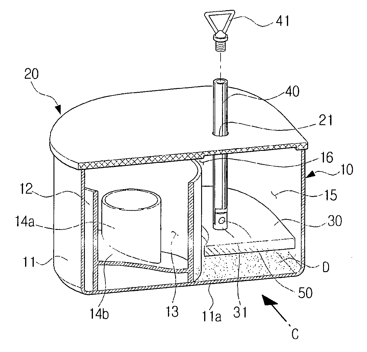
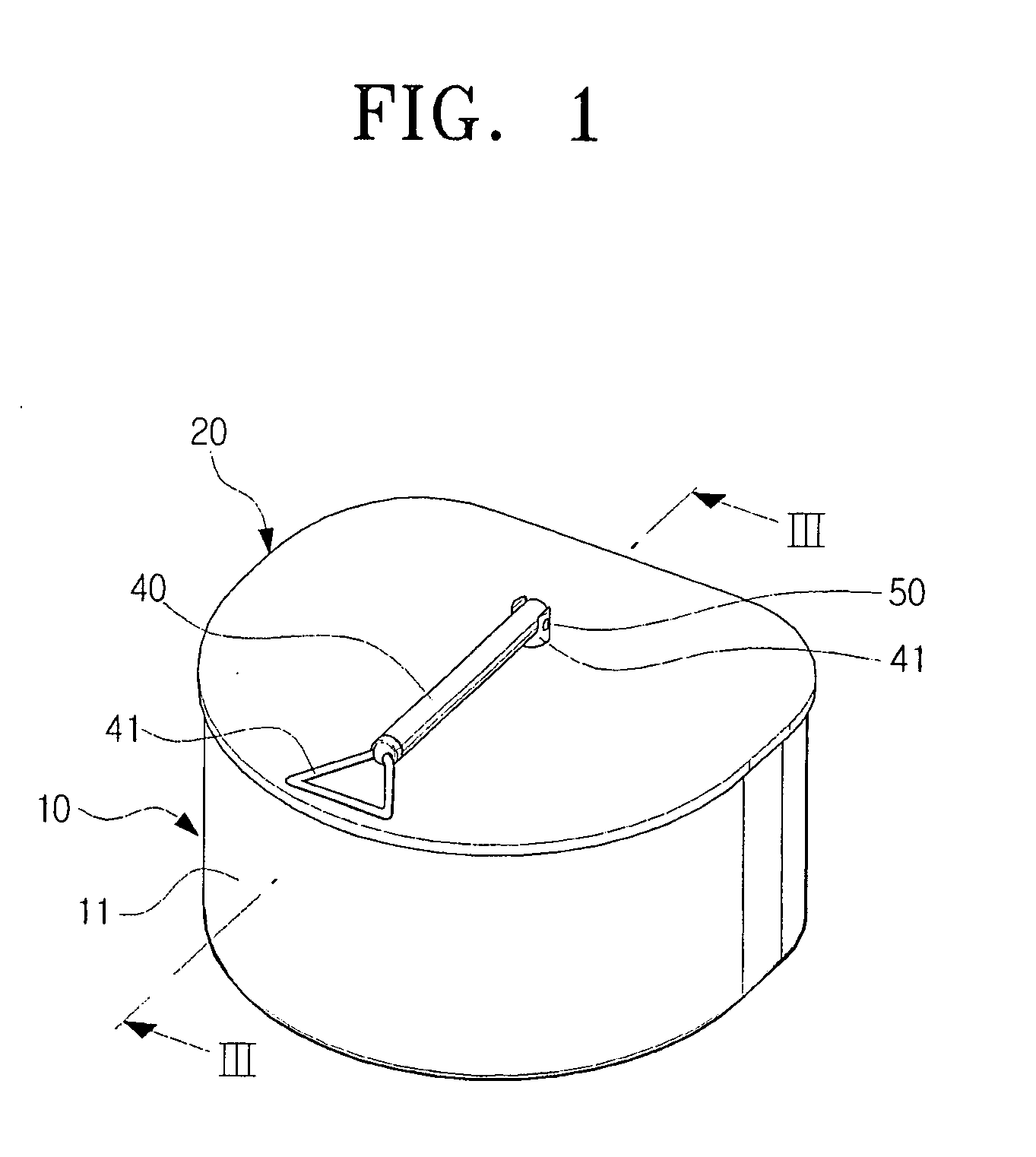
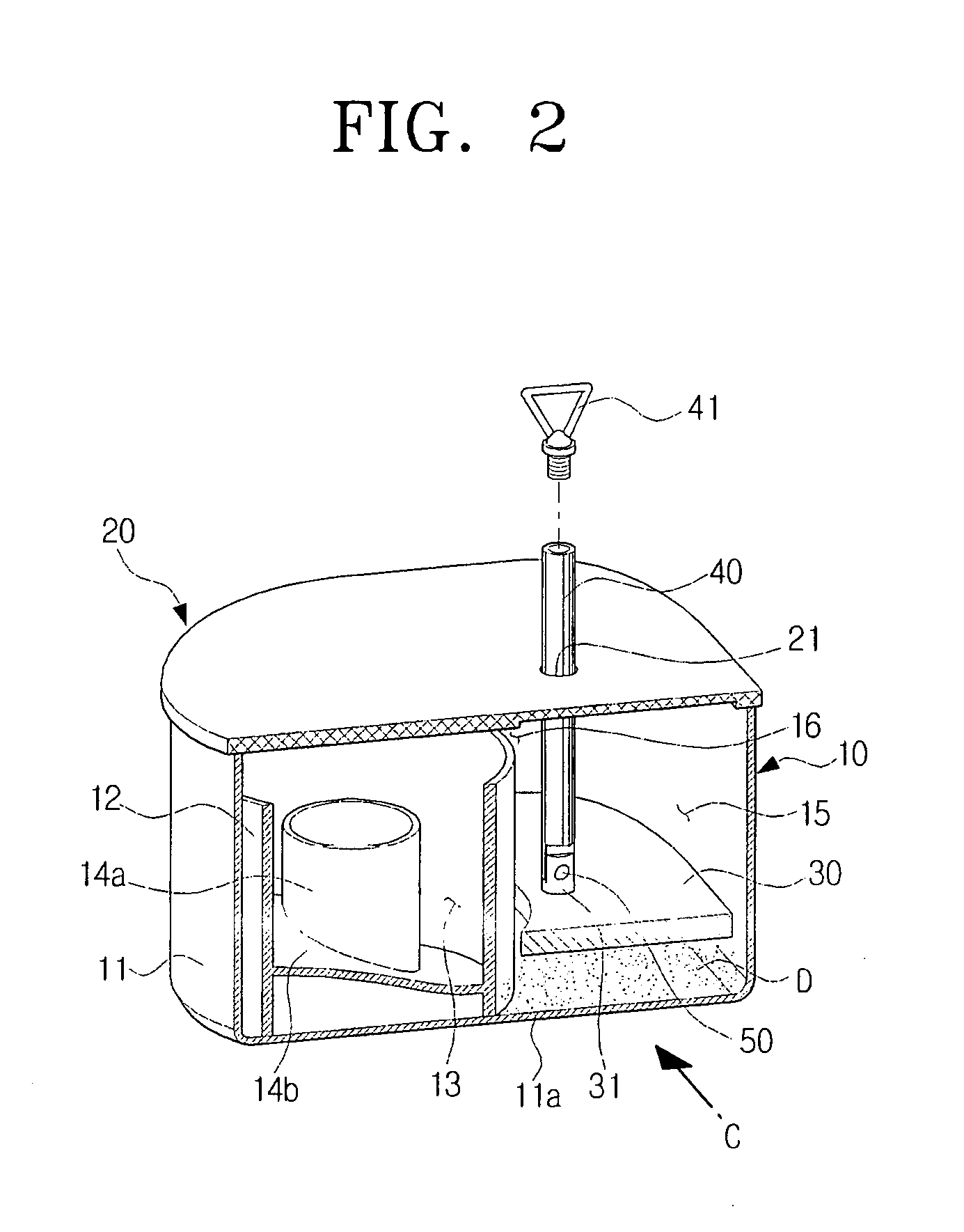
[0019]Referring to FIGS. 1 and 2, a dust collecting apparatus according to an exemplary embodiment of the present disclosure comprises a dust collecting unit 10, a cover 20, a dust compression plate 30 and a plunger 40.

[0020]The dust collecting unit 10 comprises a dust collecting case 11, a cyclone chamber 13 and a dust collecting chamber 15. The dust collecting case 11 includes an inlet (not shown) into which dust-laden air flows, and an exhaust port (not shown) through which air from which dust has been separated is discharged. The cyclone chamber 13 is separated from the dust collecting chamber 15 by a cylindrical part 12, and fluidly communicates with the inlet (not shown) and exhaust port (not shown).

[0021]The cyclone chamber 13 includes an exhaust pipe 14a which has a height lower...


PUM


Abstract

A dust collecting apparatus for a vacuum cleaner is provided. The dust collecting apparatus includes a dust collecting unit, which is detachably mounted in a main body of the vacuum cleaner and comprises an inlet and an exhaust port, to separate dust from air flowing into the inlet, collect the separated dust and discharge air from which the dust has been separated to the exhaust port; a cover to open and close an upper part of the dust collecting unit; a dust compression plate which is capable of upward and downward movement inside the dust collecting unit; and a plunger which penetrates the cover, one end of the plunger being attached to the dust compression plate by a hinge; wherein the plunger enables the dust compression plate to move upwardly and downwardly when dust compression is being performed, and the plunger is retracted and folded down toward the cover about one end of the plunger when dust compression is not being performed.

Description

CROSS-REFERENCE TO RELATED APPLICATIONS[0001]This application claims the benefit under 35 U.S.C. §119(e) of U.S. Provisional Application No. 60 / 926,832, filed Apr. 30, 2007, in the United States Patent and Trademark Office and claims the benefit under 35 U.S.C. §119(a) of Korean Patent Application No. 10-2007-0059502, filed Jun. 18, 2007, in the Korean Intellectual Property Office, the disclosure of which is incorporated herein by reference in its entirety.BACKGROUND OF THE INVENTION[0002]1. Field of the Invention[0003]The present disclosure relates to a vacuum cleaner, and more particularly, to a dust collecting apparatus for a vacuum cleaner, which collects dust from a surface to be cleaned along with drawn-in air drawn-in through a suction nozzle using a suction force generated from a suction motor, and discharges dust-laden air to the outside of the vacuum cleaner.[0004]2. Description of the Related Art[0005]In general, dust collecting apparatuses for vacuum cleaners are divided...

Claims


Application Information

Patent Timeline
Patent Type & Authority Applications(United States)
IPC IPC(8): A47L9/10
CPCA47L9/108
Inventor OH, JANG-KEUNYANG, DONG-HOUN
Owner SAMSUNG GWANGJU ELECTRONICS CO LTD
Why Eureka
Try Eureka