Electrical connection substrate, droplet discharge head, and droplet discharge apparatus

a technology of droplet discharge and droplet, which is applied in the direction of printing, inking apparatus, printed circuits, etc., can solve the problems of wires that may possibly be peeled off or broken, and the top plate member of the inkjet recording head may be at risk, and the disadvantage of the inkjet recording head may be widely encountered

Active Publication Date: 2006-09-21
FUJIFILM BUSINESS INNOVATION CORP
View PDF5 Cites 31 Cited by
  • Summary
  • Abstract
  • Description
  • Claims
  • Application Information

AI Technical Summary

Benefits of technology

[0037] If the nozzles are arranged in a matrix, the pressure chamber, the diaphragm, the piezoelectric element, etc. are arranged in a matrix to correspond to the nozzles. According to this aspect of the invention, by further arranging the electrical connection through port and the liquid supply through port in a matrix, it is possible to individually control the piezoelectric elements and individually supply the liquid to the pressure chambers.

Problems solved by technology

Such an electrical connection structure has, however, the following disadvantage.
Since a connection wiring is directly connected to the electrode film of the piezoelectric element by the thin film, the wiring may possibly be peeled off or broken due to a heat stress, a mechanical stress or the like.
Such a disadvantage may possibly not only occur to the top plate member of the inkjet recording head but also widely occur when connection target members on both sides of the substrate main body are electrically connected to each other through the through hole of the substrate main body.

Method used


Image

  • Electrical connection substrate, droplet discharge head, and droplet discharge apparatus
  • Electrical connection substrate, droplet discharge head, and droplet discharge apparatus
  • Electrical connection substrate, droplet discharge head, and droplet discharge apparatus

Examples


first embodiment

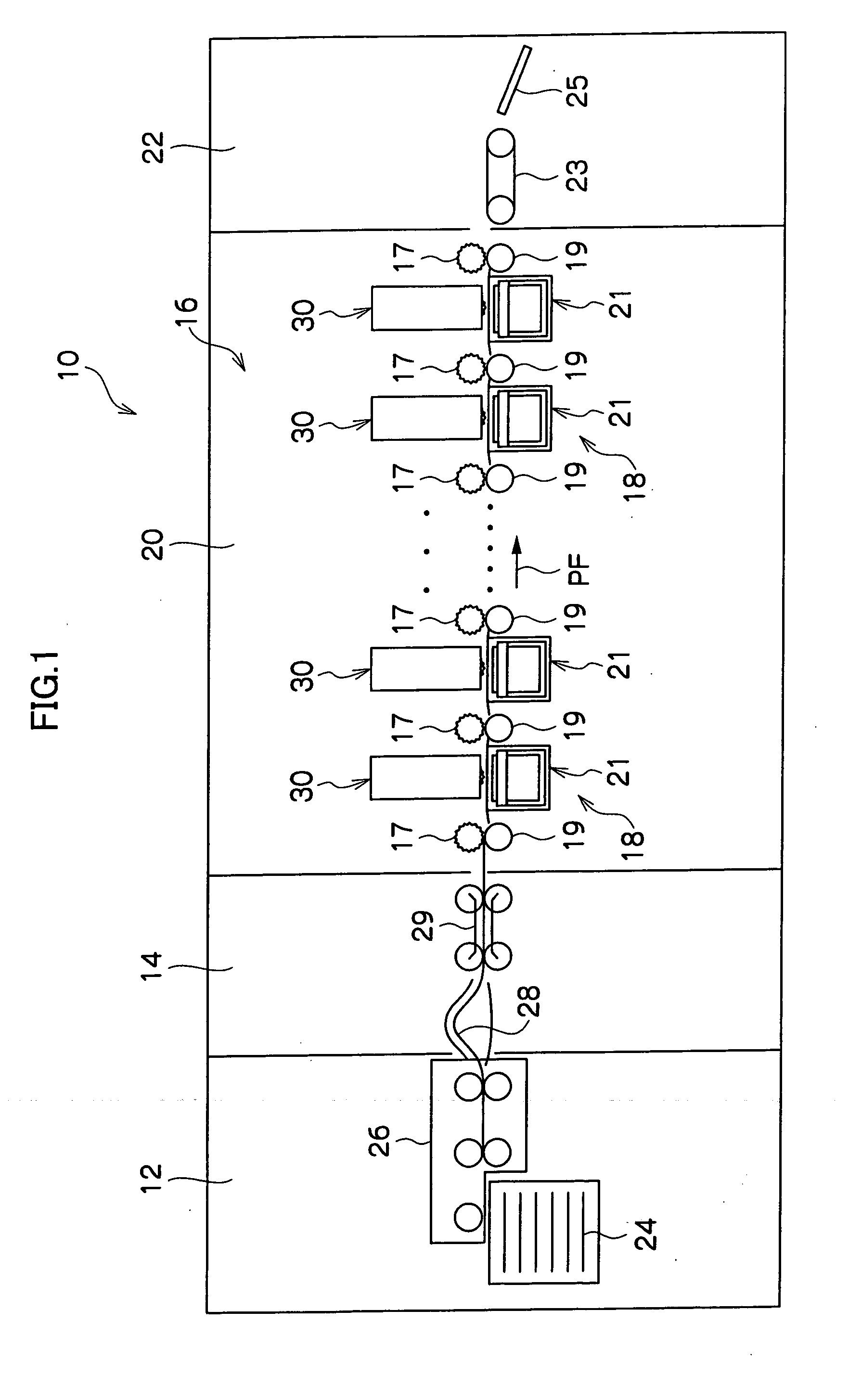
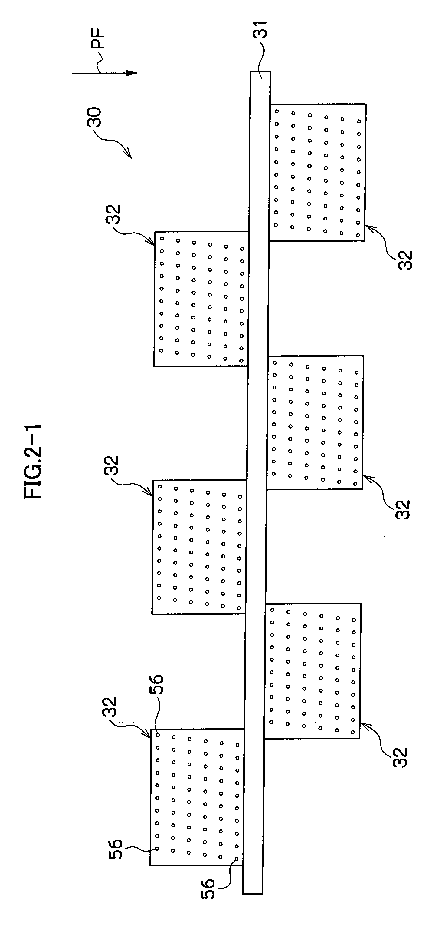
[0110] The inkjet recording head 32 of the inkjet recording apparatus 10 thus configured will next be described in detail. FIGS. 3A and 3B are schematic plan views that depict a configuration of the inkjet recording head 32 according to a FIG. 3A depicts an overall configuration of the inkjet recording head 32, and FIG. 3B depicts a configuration of one element.

[0111]FIGS. 4A to 4C depict respective sections shown in FIGS. 3A and 3B in cross sections taken along lines A-A′, B-B′, and C-C′, respectively. It should be noted, however, that a channel substrate 72 and a pool chamber member 39 are not shown therein.

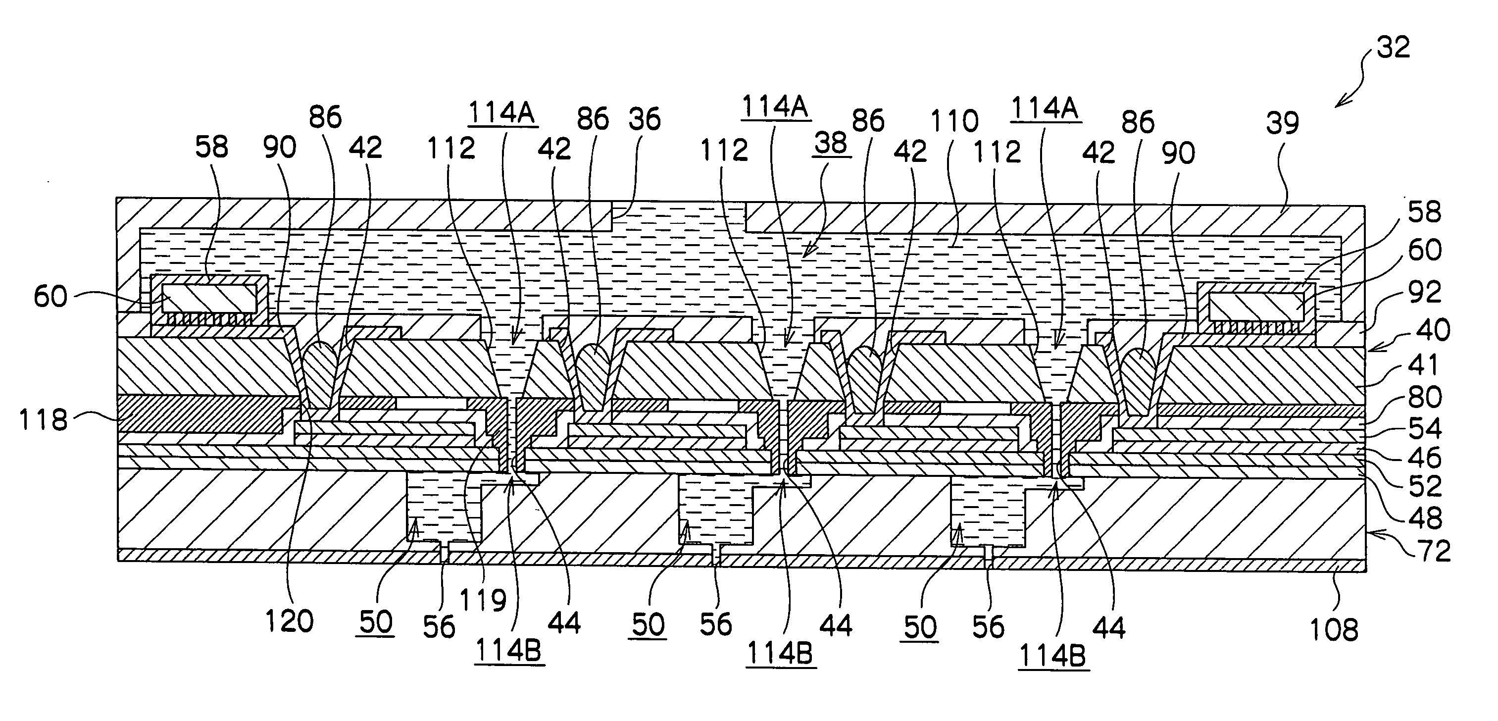
[0112]FIG. 5 is a schematic sectional view of the inkjet recording head 32 in which the inkjet recording head 32 is partially pulled out to clarify important parts of the recording head 32.

[0113] In this inkjet recording head 32, a top plate member 40 is arranged. In this embodiment, a glass top plate 41 constituting the top plate member 40 includes a plate wiring and serves...

third embodiment

[0201] A part of the manufacturing steps described in the flow (5) above, in particular, are shown in FIGS. 18-1A to 18-3G. FIG. 17 depicts an inkjet recording head 122 according to the invention obtained by these manufacturing steps.

[0202] As shown in FIG. 18-1A, in the manufacturing steps, similarly to the manufacturing steps shown in FIG. 10-1, the top plate 41 (top plate member 40) is connected (bonded) to the piezoelectric element substrate 70 by thermal compression bonding. Thereafter, before patterning the metal wirings 90, the solder 86 is mounted in each electrical connection through port 42 as shown in FIG. 18-1B. As a solder mounting method, the heated and molten solder discharge and supply method or the screen printing as well as the solder ball method for directly mounting the solder ball 86B in the electrical connection through port 42 can be used.

[0203] As shown in FIG. 18-2C, the solder 86 is subjected to reflow (e.g., at 280° C. for ten minutes), thereby spreading ...

ninth embodiment

[0218]FIGS. 25A to 27-2E depict steps of manufacturing the substrate multilayer body 212 according to the

[0219] To manufacture the first substrate 214, an Si substrate 242 is prepared as shown in FIG. 25A. And as shown in FIG. 25B, a so-called LSI process is performed on the Si substrate 242 to form the circuits 218 and the metal wirings 220, and the circuits 218 and the metal wirings 220 are protected by the insulating protection film 222. As shown in FIG. 25C, the resin protection film 224 is formed out of photosensitive resin.

[0220] Next, the second substrate 216 is manufactured. As shown in FIG. 26-1A, the Si substrate 242 is prepared. As shown in FIG. 25B, the so-called LSI process is performed on the Si substrate 242 to form the circuits 228 and the metal wirings 230, and the circuits 228 and the metal wirings 230 are protected by the insulating protection film 232. As shown in FIG. 26-1C, a resist 244 constituted by a photosensitive dry film is formed by photolithography.

[0...


PUM


Abstract

An electrical connection substrate includes a substrate main body in which an electrical connection through port is formed, and connection target members arranged on both sides of the substrate main body, respectively. The connection target members are electrically connected to each other through the electrical connection through port, and the electrical connection through port is filled with a fluidized conductive material. The fluidized conductive material thus filled can satisfactorily keep connection of the connection target members to each other through the electrical connection through port.

Description

CROSS-REFERENCE TO RELATED APPLICATION [0001] This application claims priority under 35 USC 119 from Japanese Patent Application No. 2005-74000, the disclosure of which is incorporated by reference herein. BACKGROUND OF THE INVENTION [0002] 1. Field of the Invention [0003] The present invention relates to an electrical connection substrate and a droplet discharge head. More specifically, the invention relates to a droplet discharge head including a substrate main body having an electrical connection through hole formed therein and an electrical connection substrate that electrically connects connection target members arranged on both sides of the substrate main body to each other through the electrical connection through hole. [0004] 2. Description of the Related Art [0005] As an inkjet recording head in which a diaphragm is vibrated by a piezoelectric element and ink in a pressure chamber is discharged as an ink droplet from a nozzle by this vibration, there is known an inkjet reco...

Claims


Application Information

Patent Timeline
Patent Type & Authority Applications(United States)
IPC IPC(8): B41J2/045
CPCB41J2/14233B41J2/161B41J2/1623B41J2/1628B41J2/1629B41J2/1631B41J2/1632B41J2/1634B41J2/1642B41J2/1646B41J2002/14241B41J2002/14491B41J2202/18B41J2202/20B41J2202/21H05K1/115H05K3/4652H05K2201/09509H05K2201/09827H05K2201/09572
Inventor MURATA, MICHIAKI
Owner FUJIFILM BUSINESS INNOVATION CORP
Why Eureka
Try Eureka