Storage device for laboratory samples having storage racks and a shaker

a storage device and laboratory technology, applied in the direction of mixers, biochemistry apparatuses, domestic objects, etc., can solve the problems of unfavorable shaking frequency and amplitude, unfavorable oscillatory movement of the upper end of the storage rack, noise and vibration, etc., and achieve the effect of efficient shaking of even high storage racks

Active Publication Date: 2010-11-16
LICONIC
View PDF33 Cites 14 Cited by
  • Summary
  • Abstract
  • Description
  • Claims
  • Application Information

AI Technical Summary

Benefits of technology

[0005]Hence, it is a general object of the invention to provide a storage device or a climate controlled cabinet that allows an efficient shaking of even high storage racks.
[0011]Hence, the counterweight assembly is connected to the storage rack(s) at an upper end section thereof and is driven such that it exerts an oscillatory force opposite to the shaking motion to counteract the undesired oscillations. In this manner, undesired excessive motion of the upper end of the storage rack(s) is reduced.
[0018]Hence, the object is achieved by a vertical shaking motion. This prevents a lateral oscillation of the storage rack and leads to highly homogeneous acceleration forces within the whole storage rack. A further advantage of this arrangement is the fact that an improved mixing within the small fluid volumes is achieved because of the vertical shaking motion.
[0020]In an advantageous embodiment the shaker drive comprises a rotating body driven for rotation. The rotating body has a non-horizontal end face. At least one follower member abuts against the end face and performs an up and down motion (in respect to the rotating body) while the rotating body rotates. In this matter a rotational motion can be efficiently transformed into a vertical up and down movement.

Problems solved by technology

Since the storage racks are comparatively high, undesired oscillatory movements of the upper ends of the storage racks can occur during shaking.
This limits the shaking frequency and amplitude, makes it necessary to use a very sturdy setup, and leads to undesired noise and vibrations as well as to a shaking amplitude that is different for different storage locations.

Method used


Image

  • Storage device for laboratory samples having storage racks and a shaker
  • Storage device for laboratory samples having storage racks and a shaker
  • Storage device for laboratory samples having storage racks and a shaker

Examples


Embodiment Construction

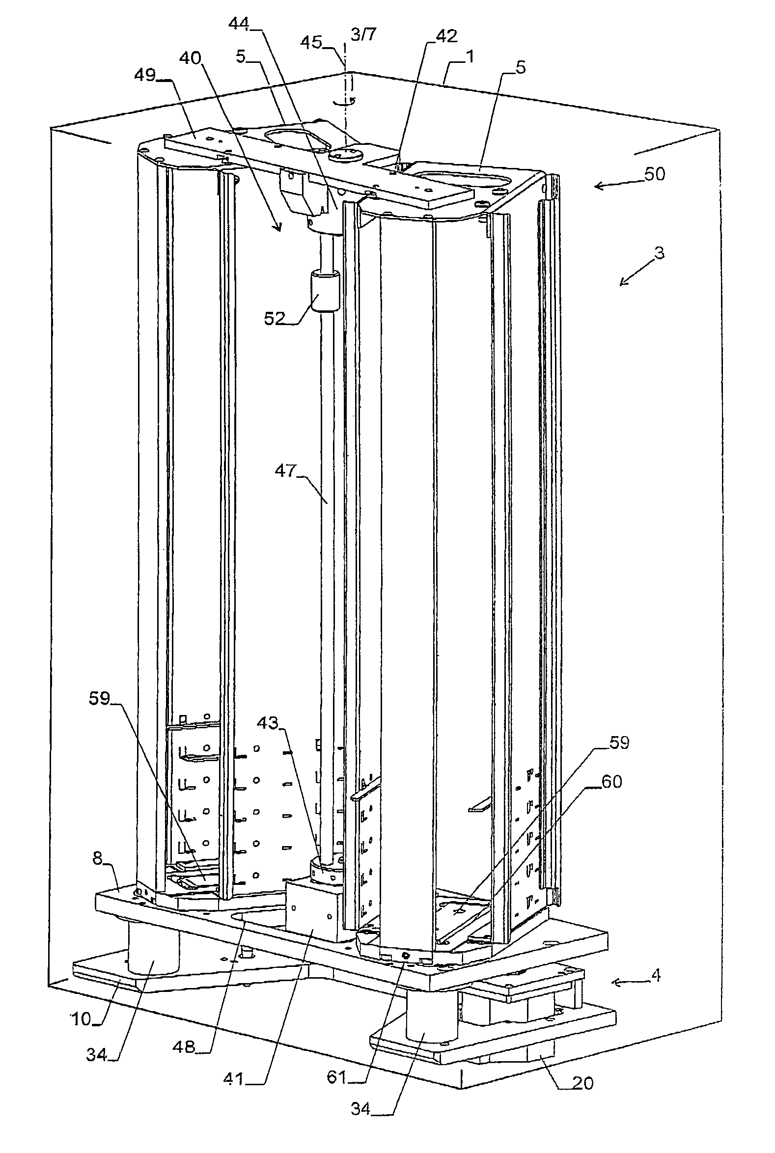
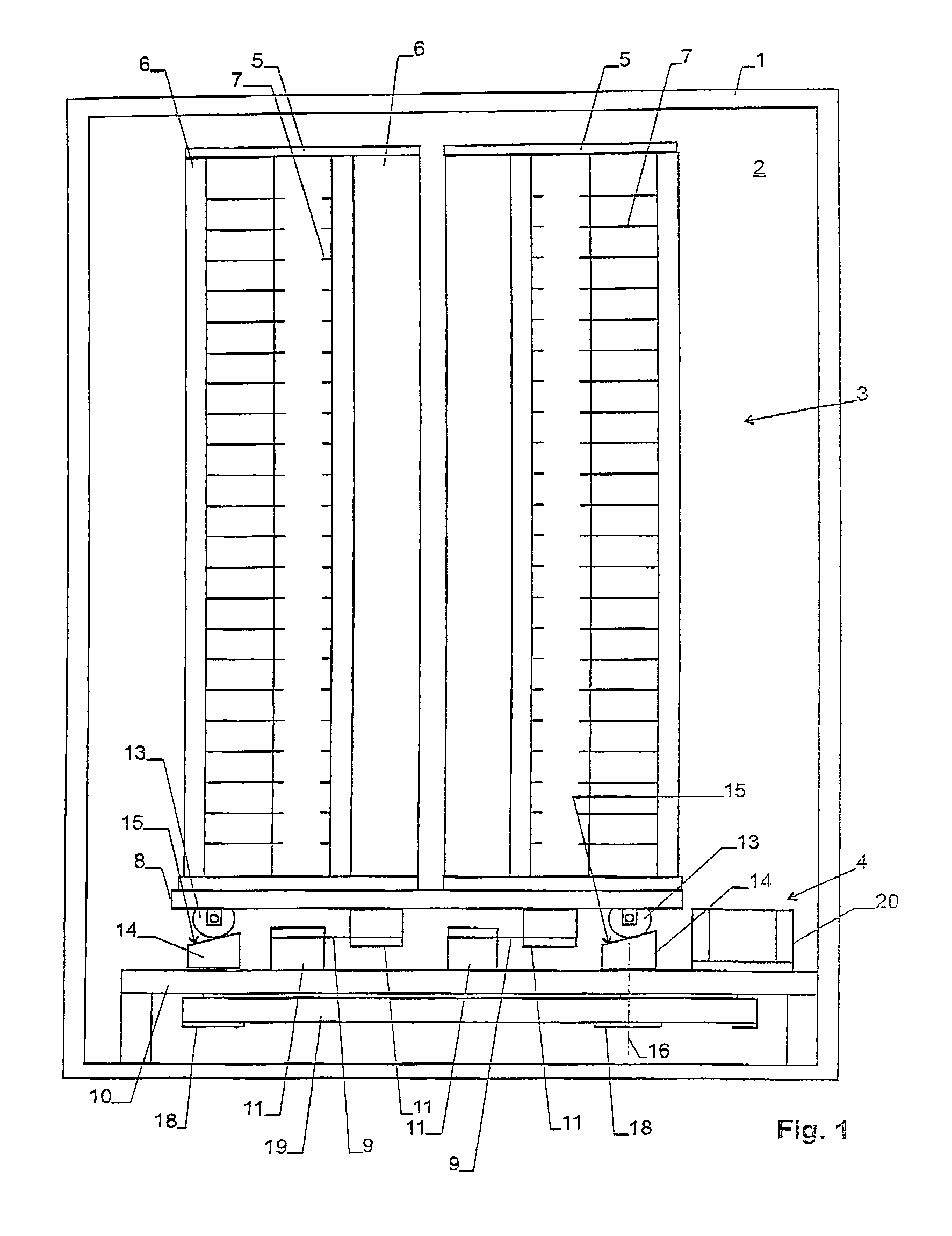
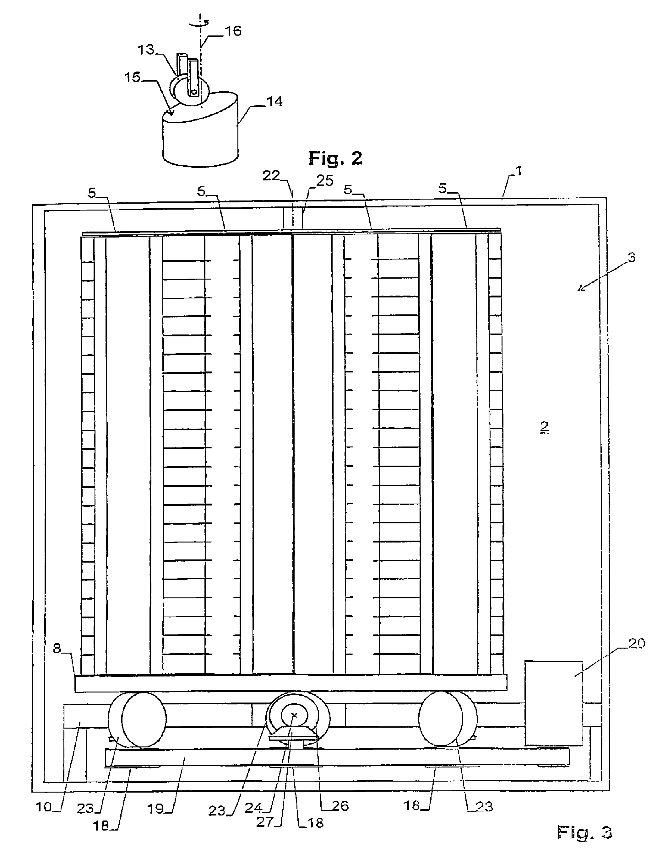
[0035]The climate controlled cabinet of FIG. 1 comprises an interior space 2 holding a storage device 3 with shaker drive 4. The climate controlled cabinet comprises means to generate a controlled climate in its interior space 2. It can be equipped for manual and / or automatic access. The climate controlled cabinet of FIG. 1 e.g. corresponds to the device shown in U.S. Pat. No. 6,478,524 and has two storage racks 5 arranged in a “V”-shaped configuration. The shaker drive of FIG. 1 is, however, also suited for storage devices with only one or substantially more storage racks. It can also be used for storage devices that are not arranged in a climate controlled cabinet. The same is true for the shaker drives 4 and storage devices 3 described further below.

[0036]Each storage rack 5 comprises two vertical side walls 6, each having a plurality of ledges 7. The ledges 7 form a corresponding number of storage locations arranged above each other for receiving the laboratory samples. In a par...


PUM


Abstract

The invention provides a storage device with storage racks and a shaker where the undesired horizontal oscillations of the upper ends of the storage racks are small. For this purpose, rotating bodies with non-horizontal end faces are provided, each of which is contacted by a follower member, with the follower member carrying out an up and down movement when the respective rotating body rotates. In a second embodiment, a moving counterweight assembly is provided that counteracts the oscillations. The counterweight assembly is connected to the upper end section of the storage racks and includes a vertically displaceable counterweight. The counterweight is mounted eccentrically on rotating tables.

Description

CROSS REFERENCE TO RELATED APPLICATIONS[0001]This application claims the priority of Swiss patent application 00813 / 05, filed May 9, 2005, the disclosure of which is incorporated herein by reference in its entirety.BACKGROUND OF THE INVENTION[0002]The invention relates to a storage device for laboratory samples comprising at least one storage rack and a shaker drive. The invention also relates to climate controlled cabinets having such a storage device.[0003]In automated essays, e.g. in microbiology, samples are stored in so-called micro titer plates having a large number of small wells. Because of the large number of probes to be investigated, a large number of plates are used in a test run. Typically, the plates are stored in tower-shaped storage racks. Each storage rack is adapted to receive a plurality of micro titer plates (or similar laboratory samples) on top of each other. For certain applications, it is necessary to shake the samples during certain time periods.[0004]EP 1 4...

Claims


Application Information

Patent Timeline
Patent Type & Authority Patents(United States)
IPC IPC(8): B01F11/00
CPCA61B10/0096B01F11/0008B01F11/0014C12M45/22B01F31/201B01F31/22
Inventor MALIN, COSMAS
Owner LICONIC
Why Eureka
Try Eureka