
Light emitting golf ball

a golf ball and light-emitting technology, applied in golf balls, non-inflatable balls, sport apparatus, etc., can solve the problems of golf balls that cannot be replaced with other lights, golf balls cannot be readily found or lost, and golf balls that cannot be emitted, so as to achieve the effect of not deteriorating the flying performance and maintaining the ball balan

Inactive Publication Date: 2010-11-16
LUMICA
View PDF11 Cites 6 Cited by
  • Summary
  • Abstract
  • Description
  • Claims
  • Application Information

AI Technical Summary

Benefits of technology

The design maintains balanced flight performance and significantly increases brightness and light-emitting time, enabling the ball to be visually identified from a distance with high light-emitting efficiency and reduced product failure rates.

Problems solved by technology

In the case where an ordinary ball is used for night play, the ball can be found if the ball is in a lighted area; however, the ball cannot be readily found or is lost if the ball is in an unlighted area.
The light-emitting golf ball has a disadvantage in that the illuminant cannot be replaced with another one.
Hence, the light-emitting body has disadvantages in that its brightness is low and its light-emitting time is short.
This leads to product failure.

Method used


Image

  • Light emitting golf ball
  • Light emitting golf ball

Examples


Embodiment Construction

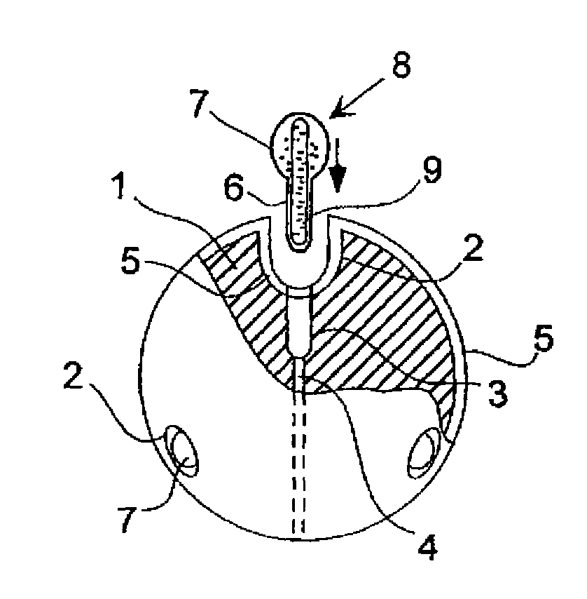
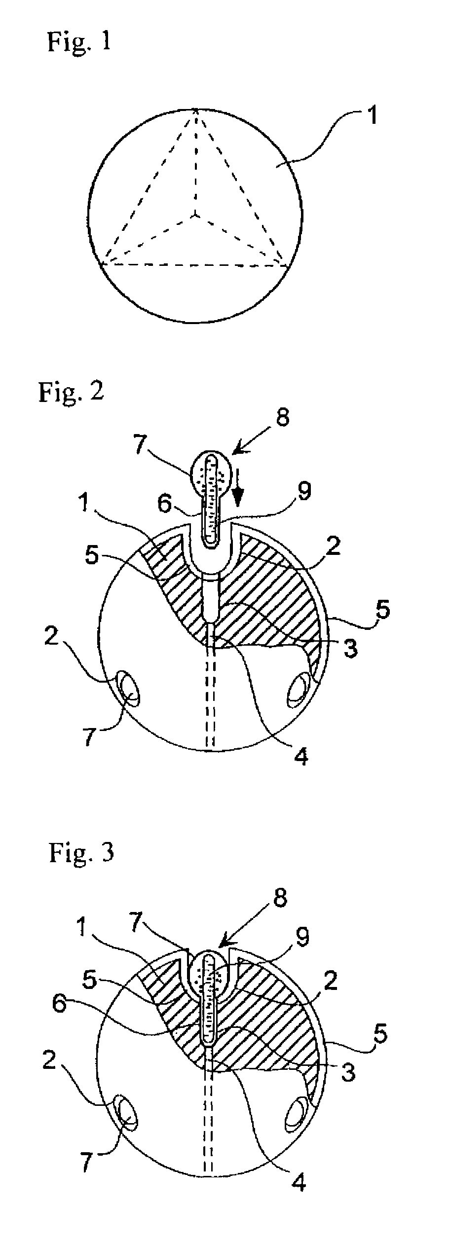
[0015]A light-emitting golf ball according to an embodiment of the present invention will now be described in detail with reference to the accompanying drawings. FIG. 2 shows the light-emitting golf ball of the present invention. Chemical light-emitting bodies 8 have a length of 18 mm. Cylindrical portions 6 have a diameter of 3 mm and a length of 9 mm. Light-emitting portions 7 are egg-shaped and have a maximum diameter of 8.0 mm and a length of 9 mm. Light-emitting bodies have a thickness of 0.3 to 0.4 mm and are blow-molded from polyethylene. Sealed glass tubes having a diameter of 2.2 mm, a length of 16 mm, and a thickness of 0.1 mm are placed in these vessels. The sealed glass vessels 9 contain dibutyl phthalate, bis(2,4,5-trichloro-6-carboisopentyloxyphenyl) oxalate (hereinafter referred to as CPPO), and 1-chloro-9,10-bis(phenylethynyl) anthracene dissolved in dibutyl phthalate. A portion of CPPO is present in a solid state. This mixture can be readily prepared by the followin...


PUM


Abstract

A light-emitting golf ball is provided. The light-emitting golf ball is characterized in that hemispherical first hollow portions extend from the surface toward the center of a core, second hollow portions having a diameter less than that of the first hollow portions extend from bottom zones of the first hollow portions toward the center of the core, narrow holes extend through the core from the second hollow portions to portions of the core that are opposed to the second hollow portions, a ball body includes a transparent cover layer extending over the core surface, chemical light-emitting bodies include sealed vessels made of a flexible transparent material, the sealed vessels have cylindrical portions and round light-emitting portions having a diameter greater than that of the cylindrical portions, the cylindrical portions are tightly fit in the second hollow portions, and the light-emitting portions are fit in the first hollow portions. The light-emitting golf ball has a brightness greater than that of conventional light-emitting golf balls and therefore can be visually identified from a distance. The light-emitting golf ball can be used many times by replacing the chemical light-emitting bodies with other ones. The balance of the ball is well maintained and therefore the flying performance thereof is not deteriorated.

Description

TECHNICAL FIELD[0001]The present invention relates to balls which have a light-emitting function and which can be used for golf play at night. The present invention particularly relates to a light-emitting golf ball that is superior in luminescence to conventional light-emitting golf balls and therefore can be visually identified from a distance. The light-emitting golf ball has substantially the same flying performance as that of ordinary balls because the balance of the ball is well maintained.BACKGROUND ART[0002]In recent years, golf courses and baseball stadiums with lighting systems have been opened. This enables night play. In the case where an ordinary ball is used for night play, the ball can be found if the ball is in a lighted area; however, the ball cannot be readily found or is lost if the ball is in an unlighted area.[0003]A light-emitting golf ball disclosed in Japanese Unexamined Patent Application Publication No. 62-2974 can be used for night play and is similar to o...

Claims


Application Information

Patent Timeline
Patent Type & Authority Patents(United States)
IPC IPC(8): A63B37/08
CPCA63B37/0003A63B43/008A63B43/06A63B37/002A63B37/0051A63B37/0052A63B37/0056A63B37/0064A63B37/0097A63B37/12
Inventor HARADA, SHIRO
Owner LUMICA
Learn More