Surgical saw blade coupler

Active Publication Date: 2010-11-16
STRYKER CORP
View PDF37 Cites 69 Cited by
  • Summary
  • Abstract
  • Description
  • Claims
  • Application Information

AI Technical Summary

Problems solved by technology

This may have the effect of compromising the clamping structure, resulting in an unintentional release or slippage of the saw blade.
Ho

Method used


Image

  • Surgical saw blade coupler
  • Surgical saw blade coupler
  • Surgical saw blade coupler

Examples


Embodiment Construction

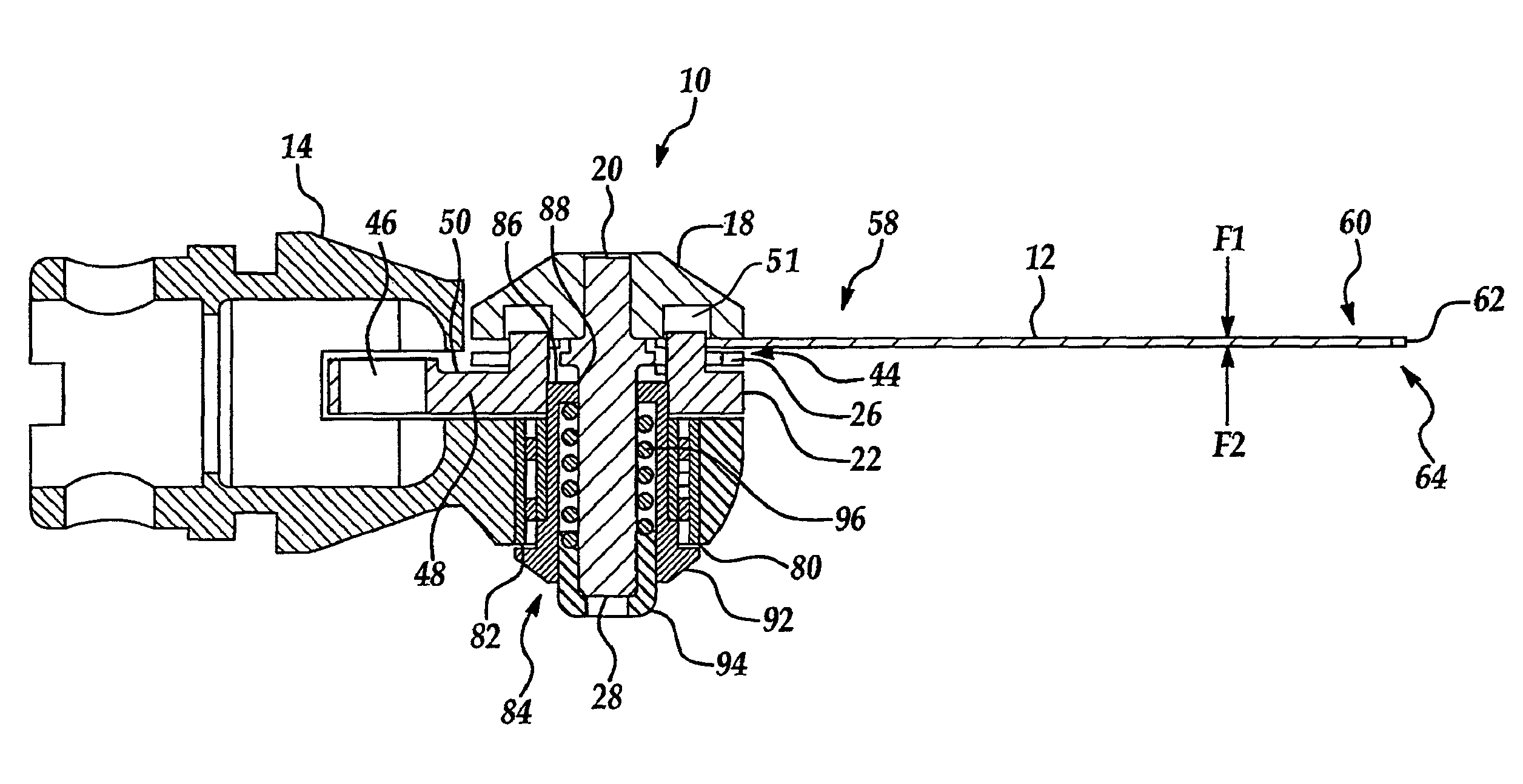
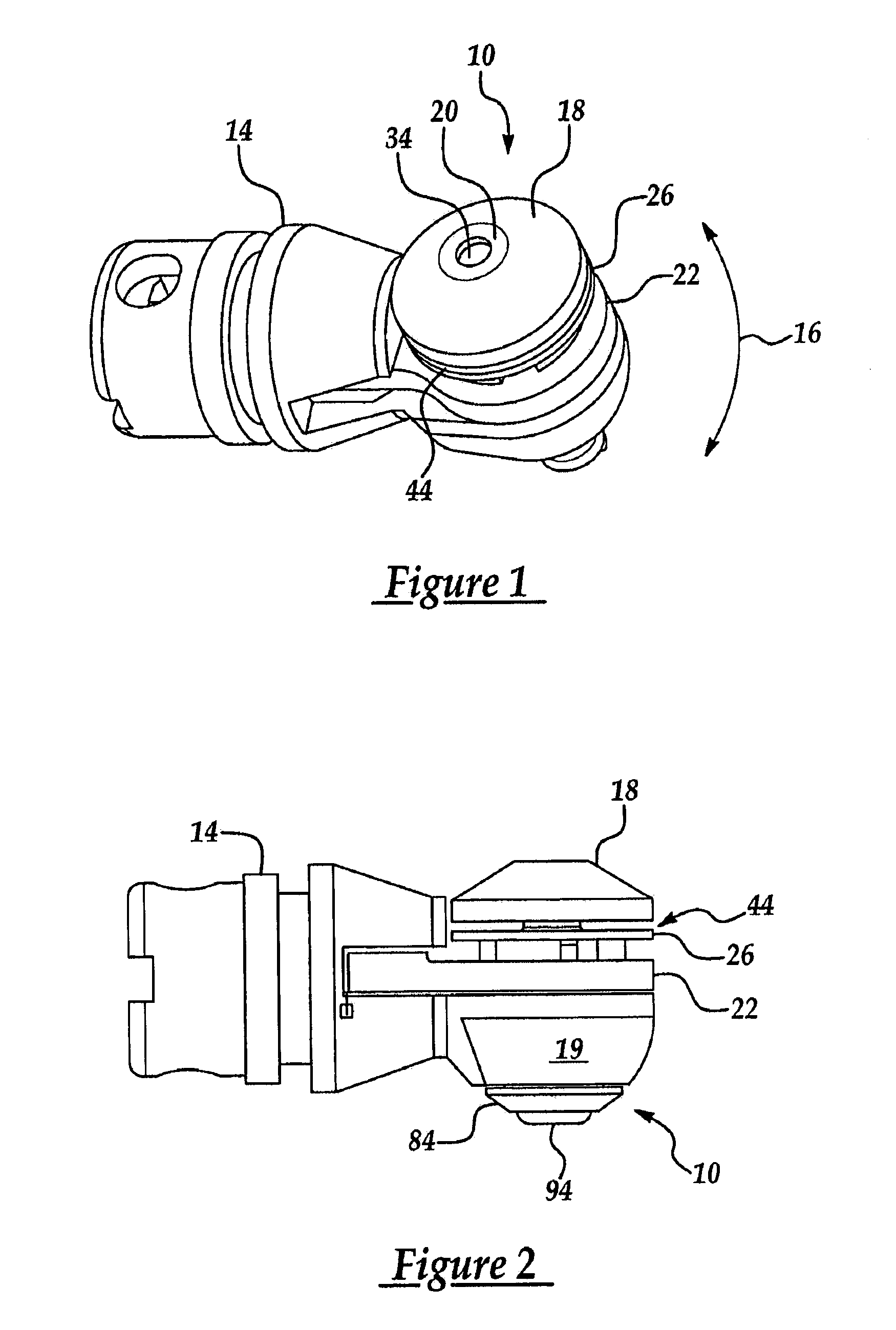
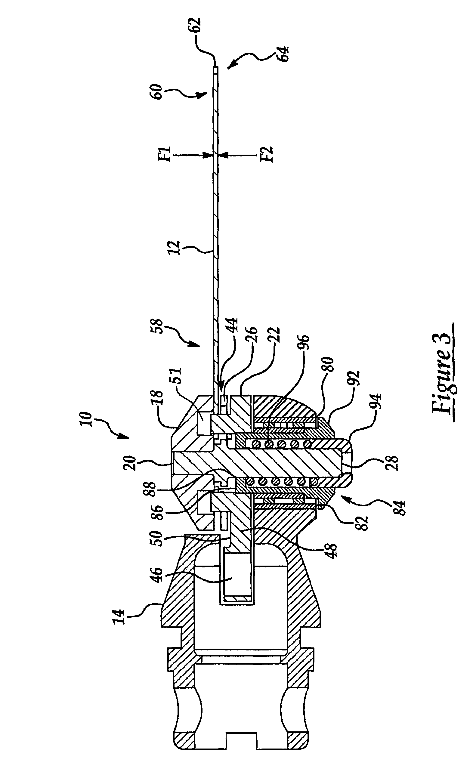
[0023]With reference to the drawings, and in operation, the present invention provides a surgical saw blade coupler 10 for use with a surgical saw blade 12. As discussed below, the surgical saw blade 12 may be of various shapes and sizes, such as a crescentic blade or a straight blade. The surgical saw blade coupler 10 is partially, rotatably contained within a housing 14 and is coupled to a motor (not shown) contained within the housing 14. The motor may be of any suitable type, e.g., pneumatic or electrical. The motor provides motion to the surgical saw blade 12. In one embodiment, the motor provides cyclical linear motion. In another embodiment, the motor provides cyclical angular motion (as shown by the arrow 16 in FIG. 1).

[0024]With specific reference to FIGS. 1, 2, 3 and 7, in one embodiment, the coupler 10 includes a cap 18, a pin 20, and a driver 22. Cap 18 and driver 22 sit on a head 19 which is the most distal end of the housing 14. Pin 20 extends though a bore 82 that ext...


PUM

PropertyMeasurementUnit
Sizeaaaaaaaaaa
Shapeaaaaaaaaaa
Heightaaaaaaaaaa

Abstract

A surgical saw blade coupler for removably holding a surgical saw blade. The surgical saw blade may be of various shapes and sizes, including, but not limited to straight or crescentic. The surgical saw blade coupler includes a cap, a pin and a driver. The driver is rotatably coupled to a motor within a housing. A cup is located within the housing within a bearing. The cap and the pin form a slot which receives a first end of the surgical saw blade. The cap and the pin also form a groove for receiving a back edge of the surgical saw blade. The surgical saw blade coupler is moveable between an open position in which the surgical saw blade may be removed, exchanged or inserted, and a closed position. A biasing spring acts against a button and the pin to close the coupler.

Description

CROSS-REFERENCE TO RELATED APPLICATIONS[0001]The present application claims priority to U.S. Provisional Application Ser. No. 60 / 425,461, filed Nov. 12, 2002.FIELD OF THE INVENTION[0002]The present invention relates generally to powered surgical cutting devices, and more particularly, to a surgical saw blade coupler for releasably holding a surgical saw blade.BACKGROUND OF THE INVENTION[0003]It is common to use powered surgical cutting devices during surgical procedures. Generally, these devices have a handle. An electric or pneumatic motor is contained within the handle. The motor drives, in a cyclical fashion, a driver. One end of a surgical blade is releasably coupled to the driver. The other end of the blade includes a cutting edge with a plurality of teeth. The surgical blade may be of various shapes, e.g., for crescentic or straight and, typically, may be mounted to the driver in various positions. Commonly, the surgical blades are interchangeable and disposable.[0004]Generall...

Claims


Application Information

Patent Timeline
IPC IPC(8): A61B17/14B23D49/00B26B1/00A61B17/00B27B5/32B27B19/00
CPCA61B17/14B27B5/32B27B19/006A61B17/1637A61B2017/00477
Inventor GANT, ANDREW
Owner STRYKER CORP
Why Eureka
Try Eureka