
Wiper blade

a wiper blade and wiper blade technology, applied in the field of wiper blades, can solve problems such as counteracting any possible resonance, and achieve the effect of preventing the tensile force from becoming too large and favorable for manufacturing

Active Publication Date: 2010-11-23
ROBERT BOSCH GMBH +1
View PDF27 Cites 36 Cited by
  • Summary
  • Abstract
  • Description
  • Claims
  • Application Information

AI Technical Summary

Benefits of technology

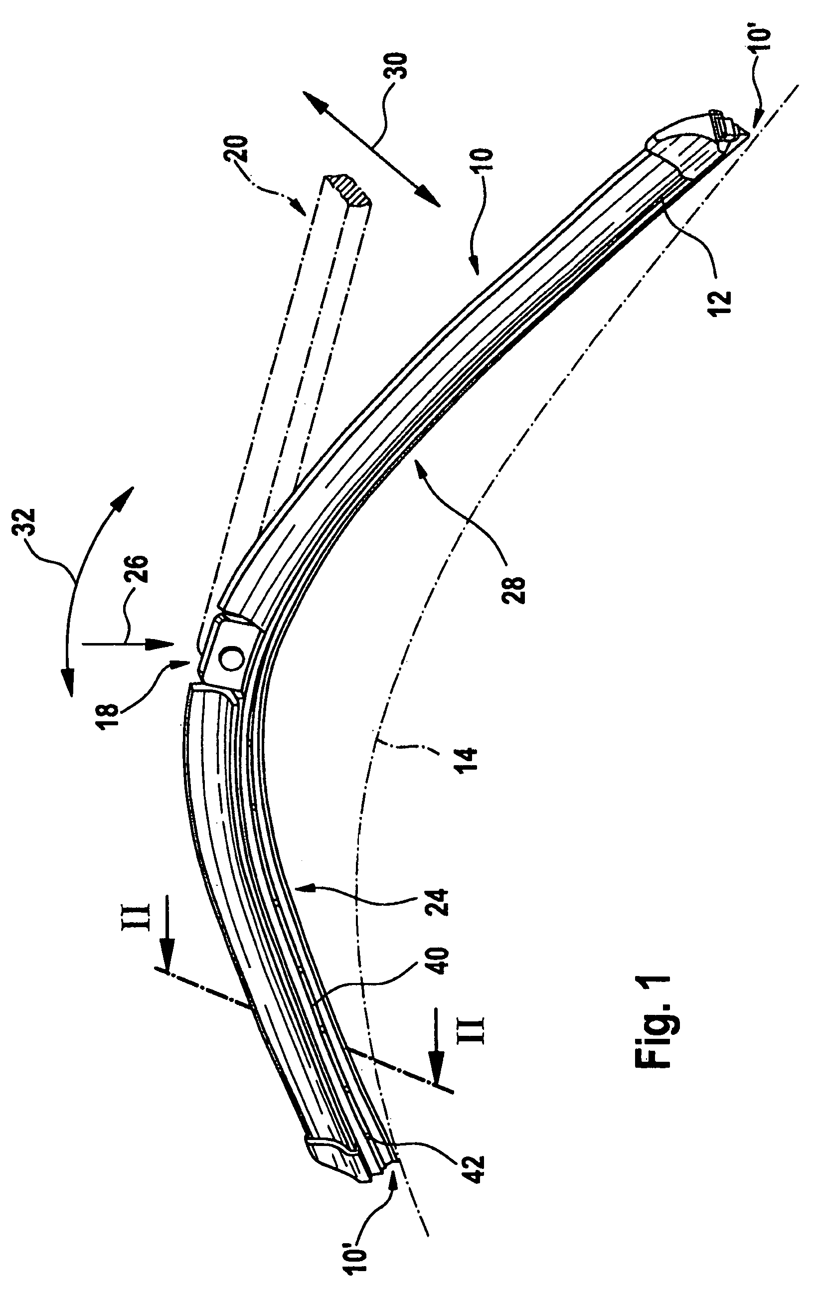
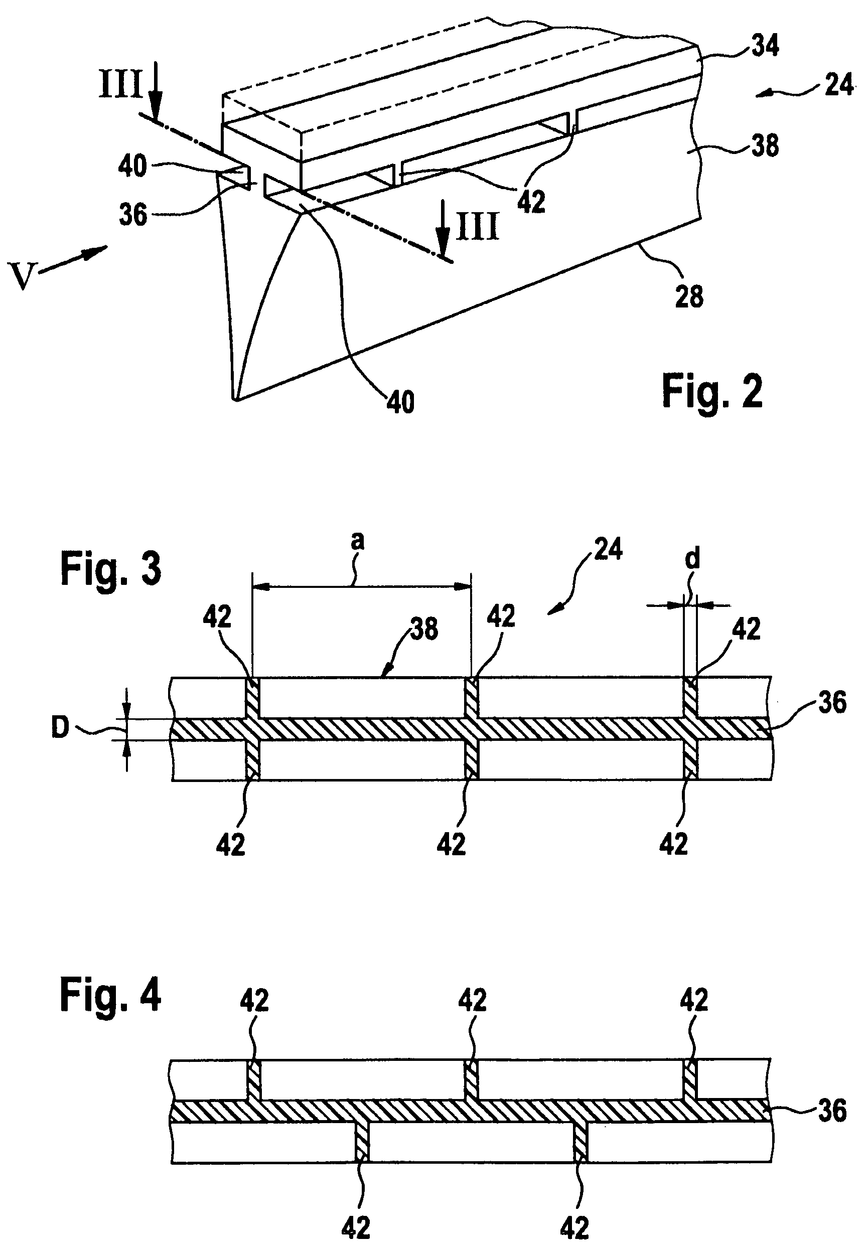
[0006]The advantage of the wiper blade in accordance with the invention is that the additional webs arranged lateral to the tilting web continuously dampen the folding process by exerting on the folding wedge with an increasing tilt an increased compressive force on the one side or an increased tensile force on the other side. As a result, this prevents, for one, as desired, the shoulder of the folding wedge from impacting against the shoulder of the wiper strip back at full speed, whereby the annoying folding-back noise can effectively be prevented. Secondly, the constant force on the folding wedge that is in the trailing position causes the folding back as such to take place reliably at the turning point. Particularly in the case of wiper blades that have already been exposed to environmental conditions for a longer period of time, there can sometimes be problems in this case.
[0007]Moreover, it has been shown that the partial interruption of the grooves located left and right next to the tilting web by the webs improves the winter suitability of the wiper blade, because ice and snow can be worked out of the grooves more effectively by the movement of the wiper blade.
[0008]Advantageous developments of the wiper blade in accordance with the invention are possible. In particular, the manufacturability of the wiper blade or the wiper blade rubber is improved if the webs are arranged perpendicular to the tilting web.
[0009]The arrangement of the webs on both sides of the tilting web guarantees that the planned trailing position is achieved in both the upward as well as the downward movement and wiping quality is equally good. If the webs are arranged offset from one another on the two sides, the forces along the tilting web are distributed uniformly. Furthermore, this counteracts any possible resonances arising from unfavorable wind conditions. A distance of the webs from one another of between 10 mm and 50 mm has turned out to be optimal.
[0013]In order to prevent the tensile force from becoming too great on the one side, the webs can be formed on only one side, i.e., each web is only formed on the wiper strip back or on the folding wedge and its other side is merely adjacent to the folding wedge or the wiper strip back or even has a small gap. Naturally, it can also be advantageous if successive webs are formed on the top or the bottom alternatingly.

Problems solved by technology

Secondly, the constant force on the folding wedge that is in the trailing position causes the folding back as such to take place reliably at the turning point.
Particularly in the case of wiper blades that have already been exposed to environmental conditions for a longer period of time, there can sometimes be problems in this case.
Furthermore, this counteracts any possible resonances arising from unfavorable wind conditions.

Method used


Image

  • Wiper blade
  • Wiper blade
  • Wiper blade

Examples


Embodiment Construction

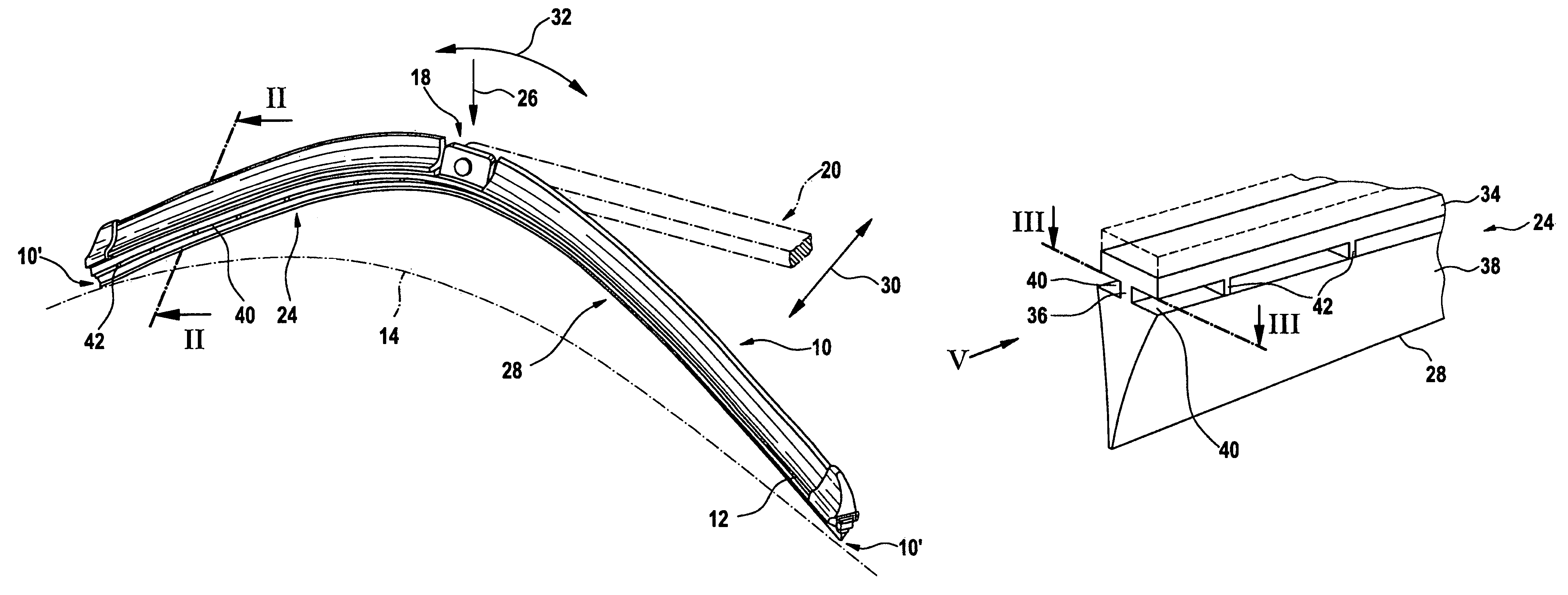
[0023]A wiper blade 10 depicted in FIG. 1 features a band-like, elongated, spring elastic single or multipart supporting element 12, which is curved in the longitudinal direction in an unstressed state. Arranged on the upper or external convex band side 16 (FIGS. 1 and 2) of the supporting element facing away from the to-be-wiped window 14 in the center section of said supporting element is, e.g., a flat, connecting device 18 that is adjacent to said band side. Said connecting device can be used to detachably connect the wiper blade 10 to a driven wiper arm 20 that is guided on the body of a vehicle. An elongated, rubber elastic wiper strip 24 is arranged on the lower or internal concave band surface or band side 22 of the curved supporting element 12 that faces the window and this wiper strip extends longitudinally axially parallel to the supporting element 12. Counter connecting means (not shown in greater detail) are provided on the free end of the wiper arm, and they cooperate w...


PUM


Abstract

A wiper blade (10) comprising a wiper strip (24) that is provided with a folding wedge (38) and a wiper strip back (34) that are connected to each other via a tilting web (36). It is proposed that additional webs (42) be arranged lateral to the tilting web (36).

Description

BACKGROUND OF THE INVENTION[0001]The invention relates to a windshield wiper device. In the case of such wiper blades with an elastic, band-like supporting element, said supporting element is supposed to guarantee the most uniform possible distribution of the wiper blade application force originating from the wiper arm on the window over the entire wiper field being covered by the wiper blade. Because of a corresponding curvature of the unstressed supporting element—i.e., when the wiper blade is adjacent to the window only at its two ends—the ends of the wiper strip that are applied completely to the window during wiper blade operation are stressed by the then tensioned supporting element on the window, even if the curvature radii of spherically curved vehicle windows change with every wiper blade position. The curvature of the wiper blade must therefore be somewhat greater than the greatest curvature measured in the wiper field on the to-be-wiped window, because during wiper operat...

Claims


Application Information

Patent Timeline
Patent Type & Authority Patents(United States)
IPC IPC(8): B60S1/38
CPCB60S1/3848B60S2001/3836
Inventor DIETRICH, JANFANGMEIER, WILHELM
Owner ROBERT BOSCH GMBH
Learn More