Reciprocating-type electric shaver

a technology of electric shaver and reciprocating blade, which is applied in the direction of metal working apparatus, etc., can solve the problems of increasing noise, problems such as noise generated by inner cutters, and achieving the effects of improving use experience, smooth and quiet operation, and small noise generated during the use of shavers

Active Publication Date: 2008-02-05
IZUMI PROD CO
View PDF12 Cites 16 Cited by
  • Summary
  • Abstract
  • Description
  • Claims
  • Application Information

AI Technical Summary

Benefits of technology

[0008]Therefore, it is an object of the present invention to provide a reciprocating-type electric shaver in which the noise caused by the reciprocating motion of the inner cutter is suppressed, assuring a smooth operation and improving the feeling of use of a reciprocating-type electric shaver.
[0014]In the above structure of the present invention, the inner cutter is provided so that it swings to the left and right with respect to the inner cutter holder (that corresponds to the float-fitting member), and the inner cutter holder is disposed so that it is movable upward and downward (i.e., free to sink inward) on the central shaft that is installed on the oscillator in an upright position. Accordingly, a minimal amount of play between the inner cutter base and oscillator in the reciprocating direction of the inner cutter is sufficient. Furthermore, there is no need for providing play in the reciprocating direction of the inner cutter in the engaging parts between the inner cutter and inner cutter holder. Consequently, the noise that is generated with the inner cutter holder when the oscillator makes its reciprocating motion is extremely small; and the noise that is generated during the use of the shaver is small, so that smooth and quiet operation is assured, and the shaver has an improved feeling of use.
[0015]In the present invention, a straight line, which passes through the supporting point (i.e., the swing center point) where the inner cutter is provided so as to be free to swing on the inner cutter holding body, and which is perpendicular to the reciprocating direction of the inner cutter, is positioned in the vicinity of the upper edge of the part of the inner cutter holder that slides with respect to the central shaft, or a straight line is positioned above this upper edge (on the inner cutter side). Thus, the height of the position of the swing center point of the inner cutter is set to be high. A sliding resistance oriented in the opposite direction from the direction of movement of the inner cutter acts on the sliding surfaces of the inner cutter, and thus a moment centered on this swing center point acts on the inner cutter. Accordingly, with the position of the swing center point set to be high as described above and being closer to the sliding surfaces of the inner cutter, such moment decreases, and the moment applied to the inner cutter holder also decreases. Consequently, the inner cutter holder can move or slide smoothly upward and downward on the central shaft, and the inner cutter makes reciprocating movement much smoothly.
[0016]Furthermore, in the present invention, the inner cutter holder that slides on the central shaft has sliding contact portions in which a sliding contact portion associated with the reciprocating direction of the inner cutter is set to be longer than a sliding contact portion associated with a direction which is perpendicular to the reciprocating direction, so that the inner cutter holder is prevented from titling in the reciprocating direction of the inner cutter. Accordingly, the inner cutter holder shows a much smaller tendency to tilt in the reciprocating direction of the inner cutter in response to the above-described moment that acts on the inner cutter.
[0017]Meanwhile, the sliding contact length of the inner cutter holder in the direction which is perpendicular to the reciprocating direction of the inner cutter is set to be short, the inner cutter tends to tilt in this direction, and a tight contact of the inner cutter with the outer cutter is assured. More specifically, since the outer cutter is ordinarily made of an extremely thin metal plate, when an external force is applied to the outer cutter in the direction which is perpendicular to the reciprocating direction of the inner cutter, the outer cutter undergoes a slight deformation and moves. In this case, since the inner cutter tilts easily in this direction, it can therefore maintain a tight contact with the outer cutter.
[0018]In the present invention, the oscillator is provided with a pair of guides, and these guides have engagement claws which restrict the rotation of the inner cutter holder about the central shaft while permitting the movement of the inner cutter holder in a direction of the central shaft or in a vertical direction, and the engagement claws further prevent the inner cutter holder from coming off of the upper end of the central shaft. With this structure, the inner cutter holder makes its upward-downward movement much smoothly. Furthermore, with this structure, the inner cutter and the inner cutter holder are maintained in an assembled state on the oscillator when the outer cutter is removed. Accordingly, the assembly and disassembly of the shaver head is easily done, and thus the structure is convenient for cleaning away the shaving debris.

Problems solved by technology

When a large amount of play is provided, problems would occur.
Namely, the noise, which is generated when the inner cutter reciprocate by the oscillator, increases.

Method used


Image

  • Reciprocating-type electric shaver
  • Reciprocating-type electric shaver
  • Reciprocating-type electric shaver

Examples


Embodiment Construction

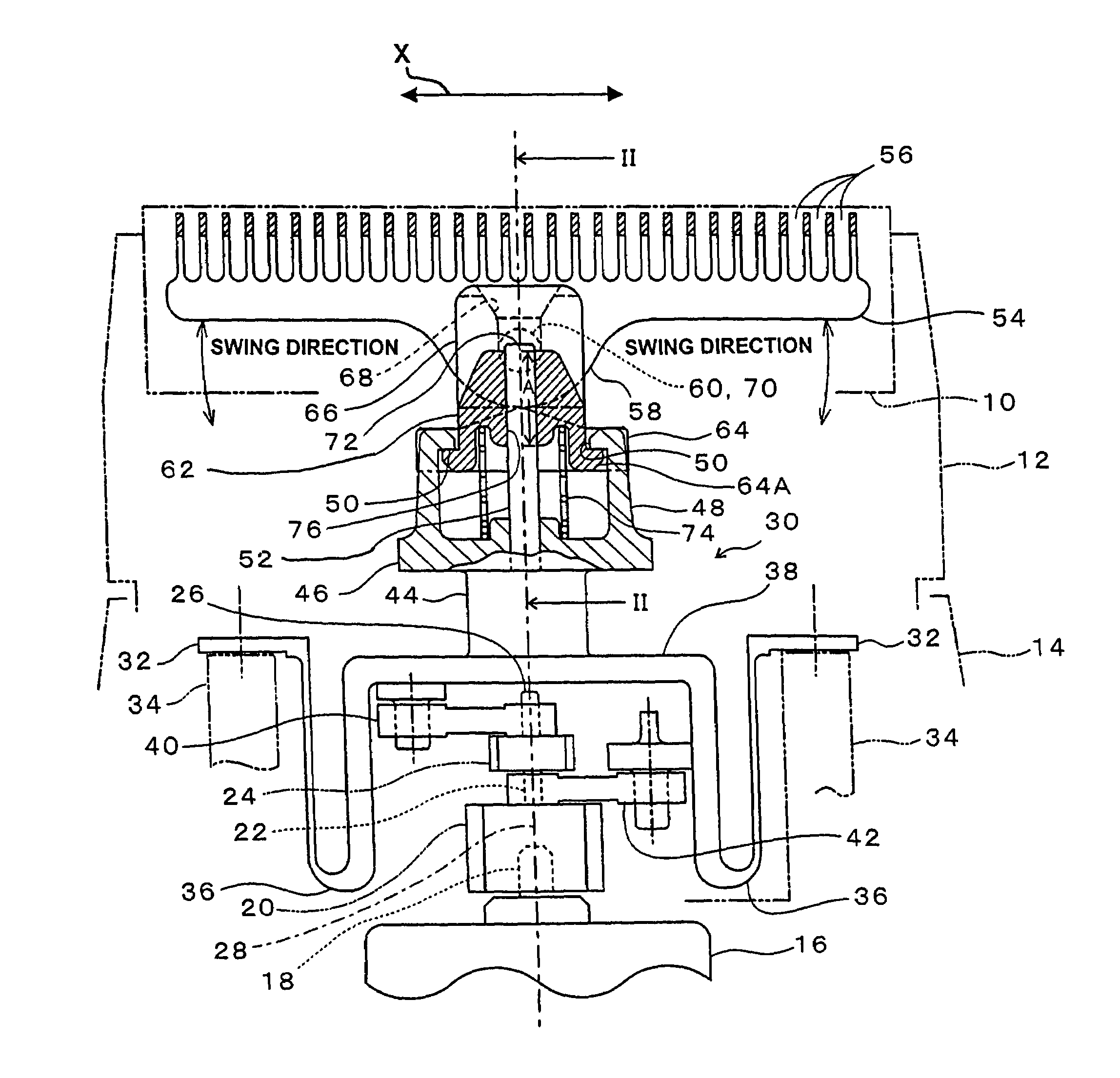
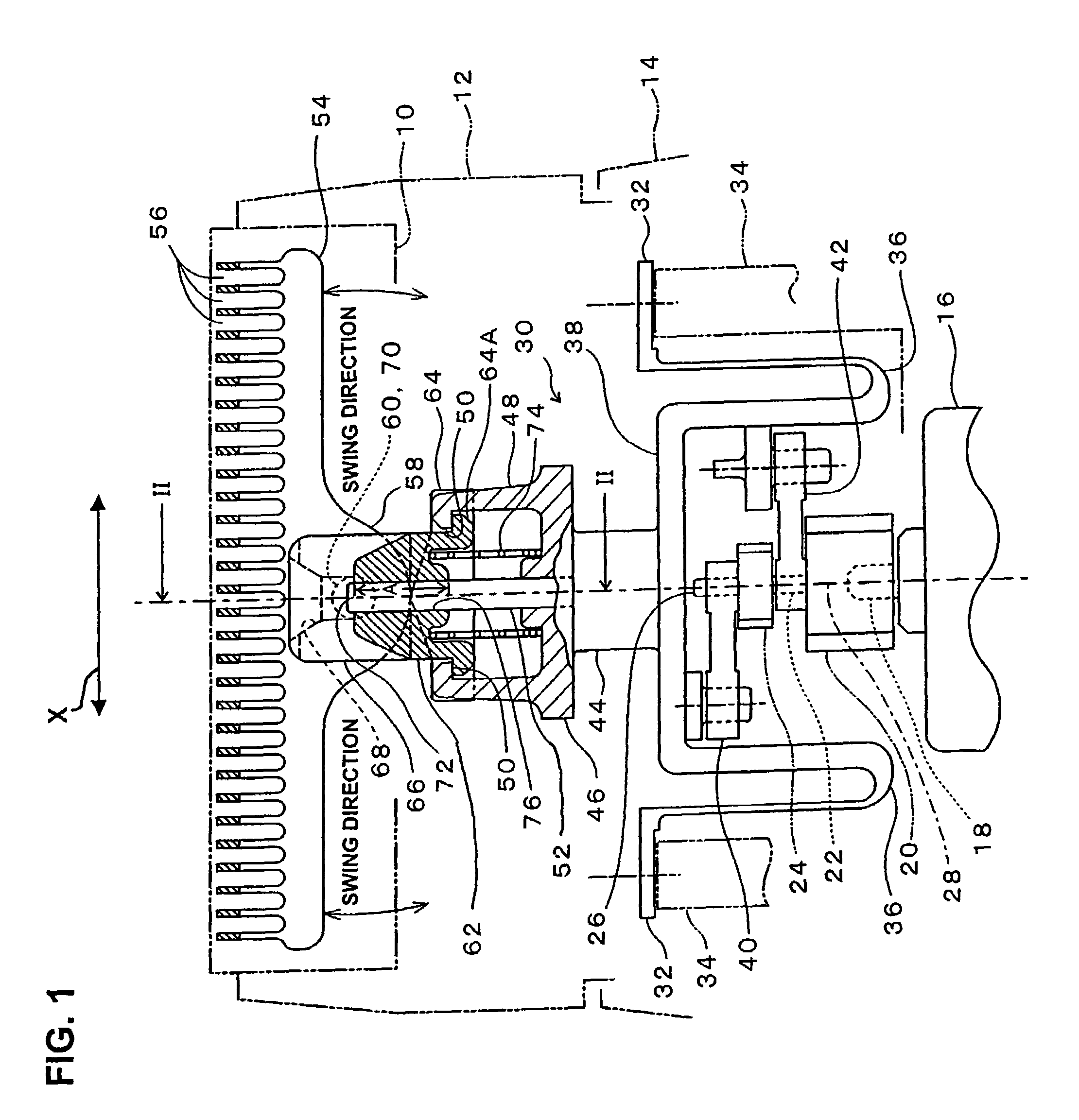
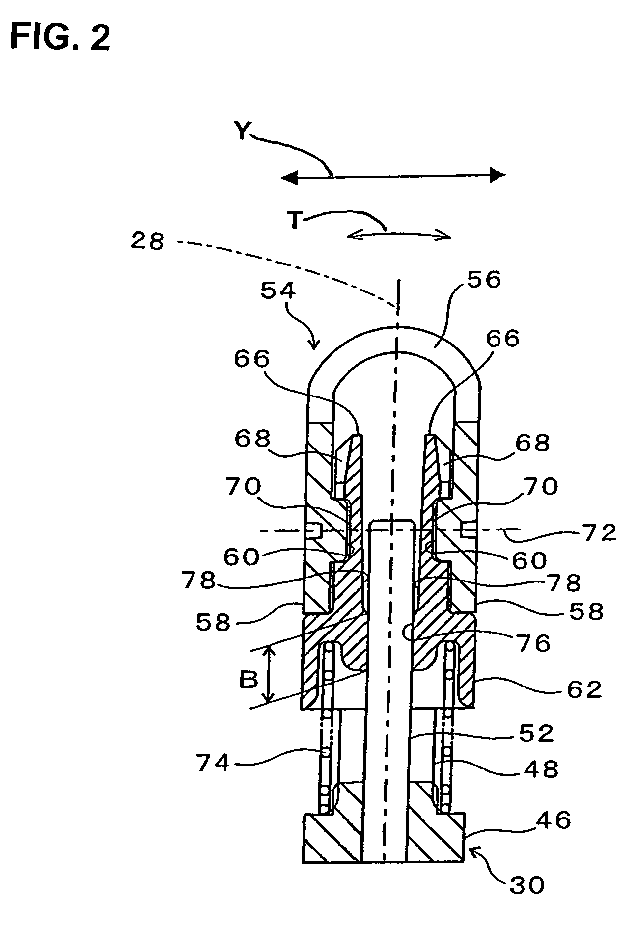
[0022]In FIG. 1, the reference numeral 10 is an outer cutter which is formed substantially in an inverted U shape (when viewed from the side (FIG. 2)) by bending into an arch shape a thin metal plate in which numerous small holes are formed. The outer cutter 10 is accommodated in a shaver head cover 12, and a part of this outer cutter 10 including its upper edge protrudes upward from the shaver head cover 12. The outer cutter 10 is installed in the shaver head cover 12 from below. While the outer cutter 10 is prevented from coming out of the shaver head cover 12 in the upward direction, the outer cutter 10 is allowed to make a specified amount of movement in downward direction.

[0023]The shaver head that includes the shaver head cover 12 is detachably mounted on the shaver main body 14, or it is provided so that it is opened and closed with respect to the shaver main body 14.

[0024]An electric motor 16, battery, switch, control circuit and the like are provided inside the shaver main ...


PUM


Abstract

A reciprocating-type electric shaver including an outer cutter having an inverted U shape as seen from a side thereof and an inner cutter making a reciprocating motion while making sliding contact with an inside surface of outer cutter, and further including: an oscillator making a reciprocating motion by a motor installed inside the main body of the shaver; a central shaft provided in an upright position on the oscillator and rises toward the inside of the outer cutter; an inner cutter holder disposed in a slidable manner on the central shaft so that the inner cutter holder holds the inner cutter thereon and the inner cutter swings about a straight line that is perpendicular to the reciprocating direction of the inner cutter; and a spring compressedly installed between the oscillator and the inner cutter holder.

Description

BACKGROUND OF THE INVENTION[0001]1. Field of the Invention[0002]The present invention relates to a reciprocating-type electric shaver in which an inner cutter reciprocates inside an outer cutter, thus shaving hair and the like.[0003]2. Description of the Related Art[0004]In reciprocating-type electric shavers, an inner cutter, as well known, reciprocates while making sliding contact with the inside surface of an outer cutter which has substantially an inverted U shape when seen from the side, thus cutting hair entered in the slits formed in the outer cutter. In such electric shavers, the outer cutter inclines and sinks inward (on sinks into the shaver head) when it is moved during the shaving along the curved surfaces of the skin, so that the cutter surface of the outer cutter makes tight contact with the skin, thus increasing the hair cutting capability. In this structure, the inner cutter also inclines and sinks inward together with the outer cutter.[0005]Japanese Patent Applicati...

Claims


Application Information

Patent Timeline
Patent Type & Authority Patents(United States)
IPC IPC(8): B26B19/02
CPCB26B19/046B26B19/063B26B19/02B26B19/04
Inventor SHIMIZU, TETSUHIKO
Owner IZUMI PROD CO
Why Eureka
Try Eureka