
Wall mount usable with display apparatus

a technology for display apparatuses and wall mounts, which is applied in curtain suspension devices, television systems, instruments, etc., can solve the problems of increasing demand for wall mounts and high cost of conventional wall mount components and assembly, and achieves the effect of simplifying the tilting structure and easy tilting of the display apparatus

Inactive Publication Date: 2009-02-24
SAMSUNG ELECTRONICS CO LTD
View PDF19 Cites 16 Cited by
  • Summary
  • Abstract
  • Description
  • Claims
  • Application Information

AI Technical Summary

Benefits of technology

The present invention provides a wall mount for a display apparatus that allows for easy tilting of the display apparatus through a simplified tilting structure. The wall mount includes a base, supporting bracket, rotating bracket, and elastic member to adjust the tilt angle of the rotating bracket. The elastic member may comprise a shaft, roller, and spring. The wall mount may also include an auxiliary shaft and auxiliary roller to support the elastic member. The tilting bracket assembly includes a fixed bracket, tilting bracket, and elastic member to apply an elastic force to support the tilting bracket at a desired tilt angle with respect to the fixed bracket. The technical effects of the present invention include improved tilting convenience and stability of the display apparatus.

Problems solved by technology

Thus, a demand for a wall mount is increasing, since the wall mount is less restricted by an installing place and occupies a small amount of space by installing the display apparatus on the wall.
However, the conventional wall mount having such a structure comprises a complicated structure of the angle adjusting member for adjusting the tilt angle of the display apparatus.
Further, the angle adjusting member of the conventional wall mount requires many components, and thus it costs a lot for the components and assembly of the conventional wall mount.

Method used


Image

  • Wall mount usable with display apparatus
  • Wall mount usable with display apparatus
  • Wall mount usable with display apparatus

Examples


Embodiment Construction

[0023]Reference will now be made in detail to the embodiments of the present general inventive concept, examples of which are illustrated in the accompanying drawings, wherein like reference numerals refer to like elements throughout. The embodiments are described below in order to explain the present general inventive concept while referring to the figures.

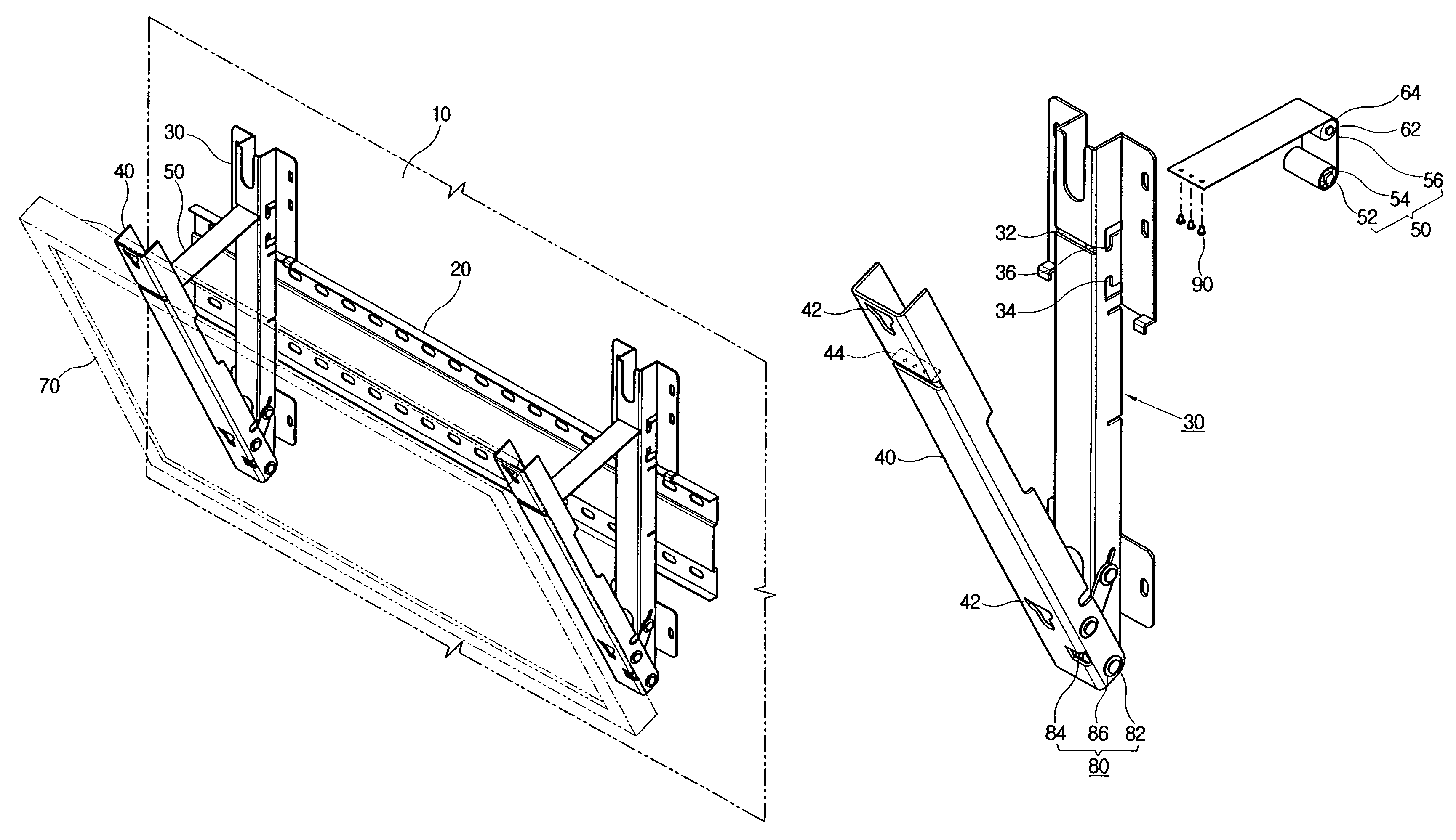
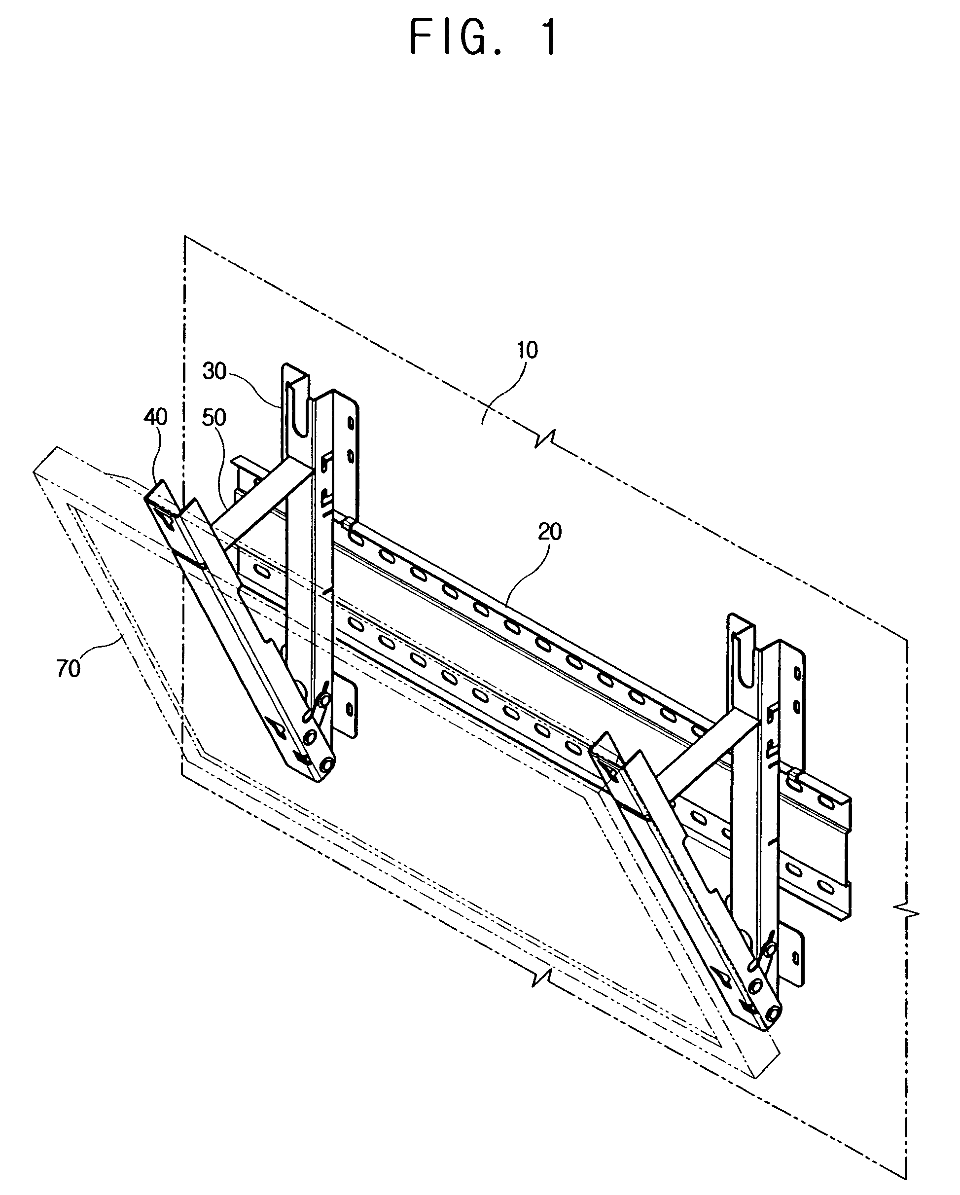
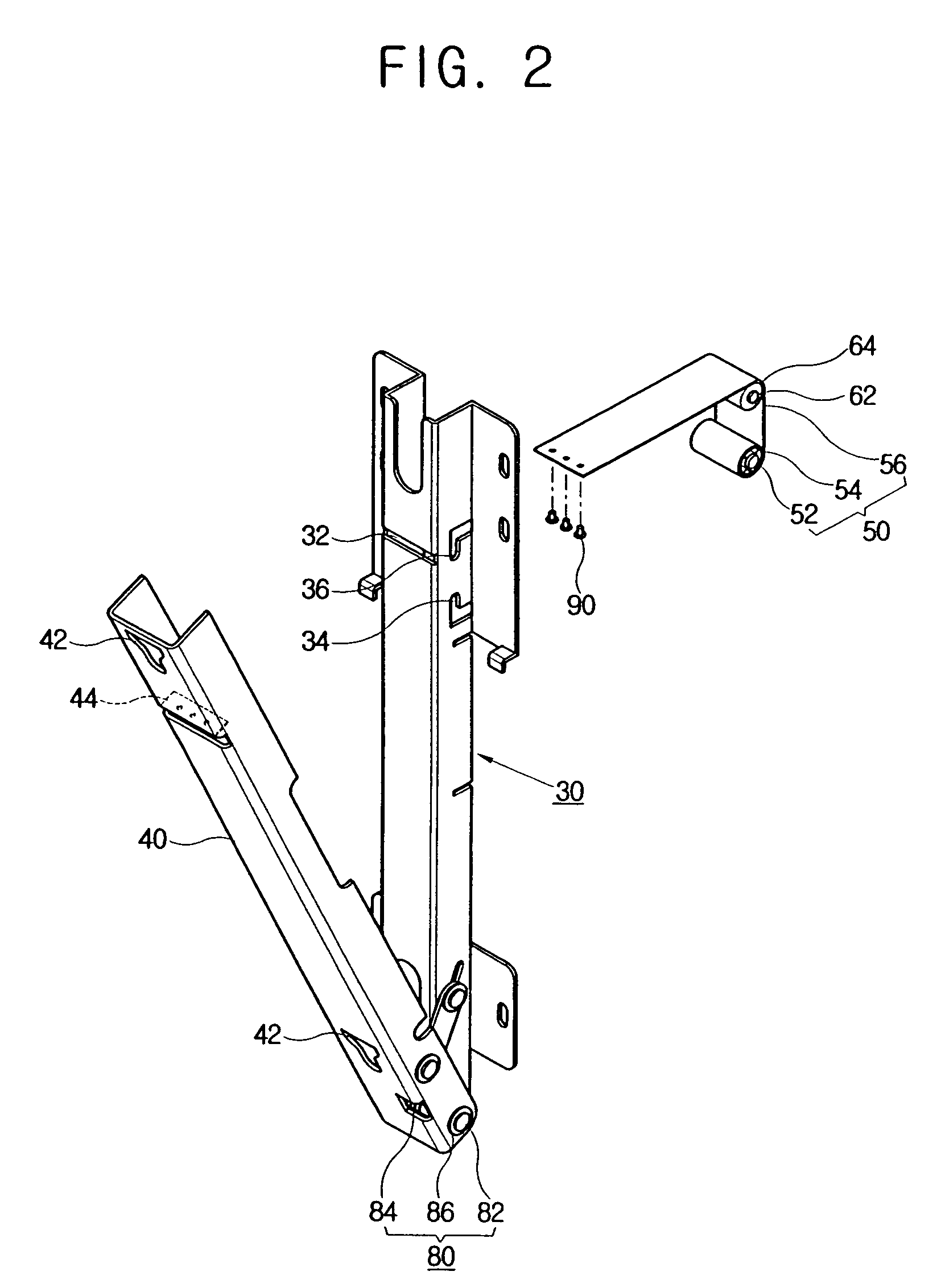
[0024]Referring to FIGS. 1 through 3, a wall mount usable with a display apparatus 70 according to an embodiment of the present general inventive concept comprises a base 20 attached to a wall 10, a supporting bracket 30 supported by the base 20, a rotating bracket 40 tiltably coupled to the supporting bracket 30 and mounted with the display apparatus 70, an elastic member 50 placed between the supporting bracket 30 and the rotating bracket 40 to elastically expand or contract according to a rotation of the rotating bracket 40 to adjust a tilt angle of the rotating bracket 40 with respect to the supporting bracket 30.

[0025]The ba...


PUM


Abstract

A wall mount usable with a display apparatus to mount the display apparatus on a wall, includes a base to attach to the wall, a supporting bracket supported by the base, a rotating bracket tiltably coupled to the supporting bracket and on which the display apparatus is mounted, and an elastic member provided between the supporting bracket and the rotating bracket to expand or contract according to rotation of the rotating bracket to adjust a tilt angle of the rotating bracket. Thus, the wall mount easily tilts the display apparatus through a simplified tilting structure.

Description

CROSS-REFERENCE TO RELATED APPLICATIONS[0001]This application claims the benefit under 35 U.S.C. § 119 of Korean Patent Application No. 2004-77163, filed on Sep. 24, 2004, in the Korean Intellectual Property Office, the disclosure of which is incorporated herein in its entirety by reference.BACKGROUND OF THE INVENTION[0002]1. Field of the Invention[0003]The present general inventive concept relates to a wall mount usable with a display apparatus, and more particularly, to a wall mount usable with a display apparatus having an improved tilting structure to tilt the display apparatus.[0004]2. Description of the Related Art[0005]A display apparatus refers to various kinds of apparatuses visually displaying data of text, images, or the like on a display panel.[0006]Flat panel display apparatuses, such as a PDP (plasma display panel) or an LCD (liquid crystal display) are widely used as televisions or monitors, and research and development of the flat panel display apparatuses are being ...

Claims


Application Information

Patent Timeline
Patent Type & Authority Patents(United States)
IPC IPC(8): E04G3/00
CPCF16M13/02G09F7/20F16M11/10F16M2200/041H04N5/655
Inventor SHIN, YONG-HA
Owner SAMSUNG ELECTRONICS CO LTD
Learn More