Combination spar and trunnion structure for a tilt rotor aircraft

a technology of trunnion structure and tilt rotor, which is applied in the field of rotorcraft, can solve the problems that the concept of outboard wings on tilt rotor aircraft has been largely ignored, and achieve the effect of facilitating the tilting of the nacell

Active Publication Date: 2011-12-27
KAREM ABE
View PDF6 Cites 16 Cited by
  • Summary
  • Abstract
  • Description
  • Claims
  • Application Information

AI Technical Summary

Benefits of technology

[0013]The present invention provides apparatus, systems and methods in which an aircraft is equipped with a spinnion coupling an inboard wing to a tilting nacelle. The spinnion is advantageously configured to extend across the nacelle from an inboard junction to an outboard junction, and terminates inside the inboard wing. This provides an efficient lightweight structure to support a nacelle and facilitate tilting of the nacelle.

Problems solved by technology

To this end, the concept of outboard wings on tilt rotor aircraft has been largely ignored due to the high bending moments that applied to the conversion spindle.

Method used


Image

  • Combination spar and trunnion structure for a tilt rotor aircraft
  • Combination spar and trunnion structure for a tilt rotor aircraft
  • Combination spar and trunnion structure for a tilt rotor aircraft

Examples


Embodiment Construction

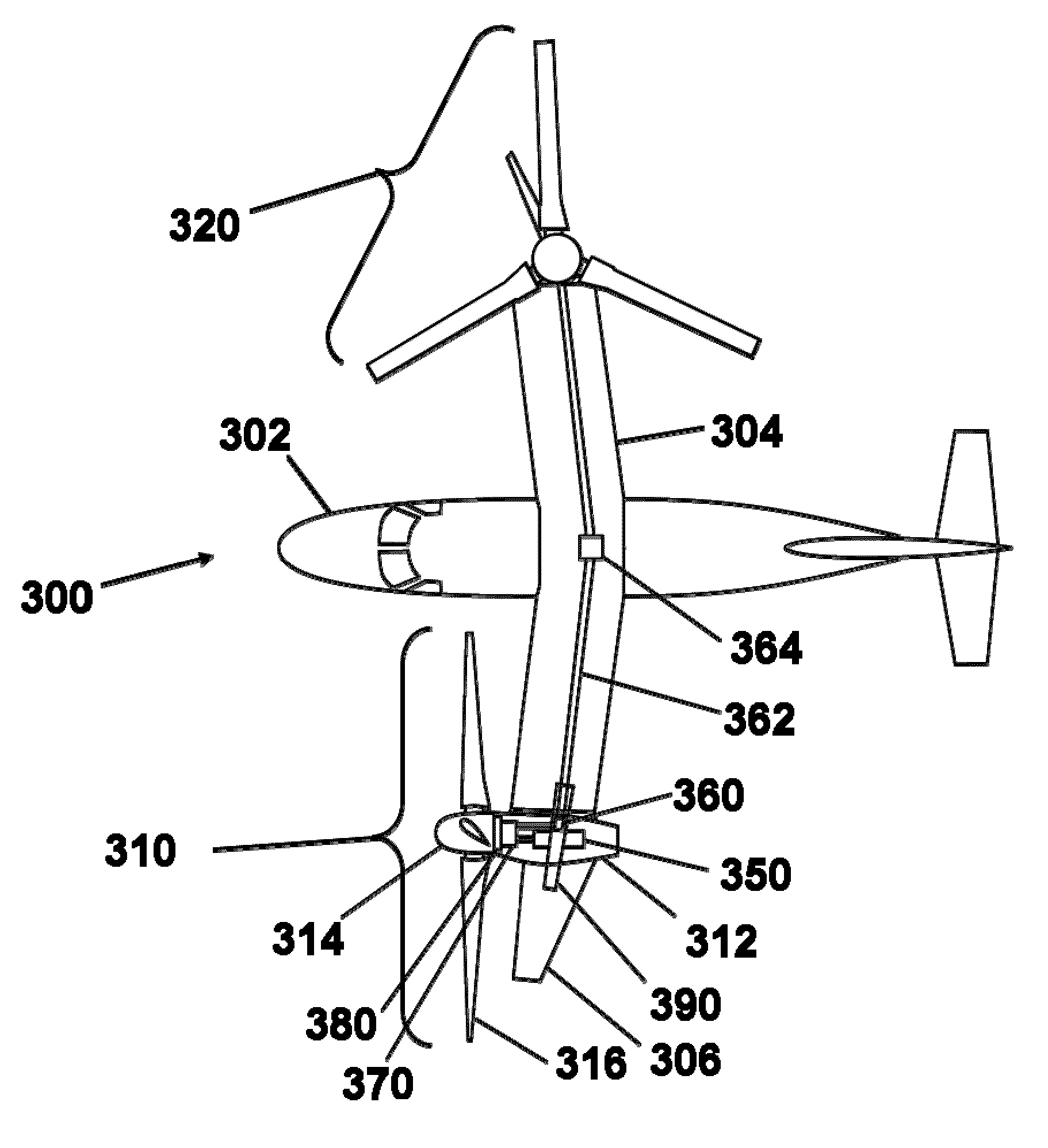
[0024]The present invention provides apparatus, systems and methods in which a conversion spindle disposed at least partially within an inboard wing extends across a nacelle to an outboard junction. As used herein, the resulting integrated structure is termed a “spinnion”.

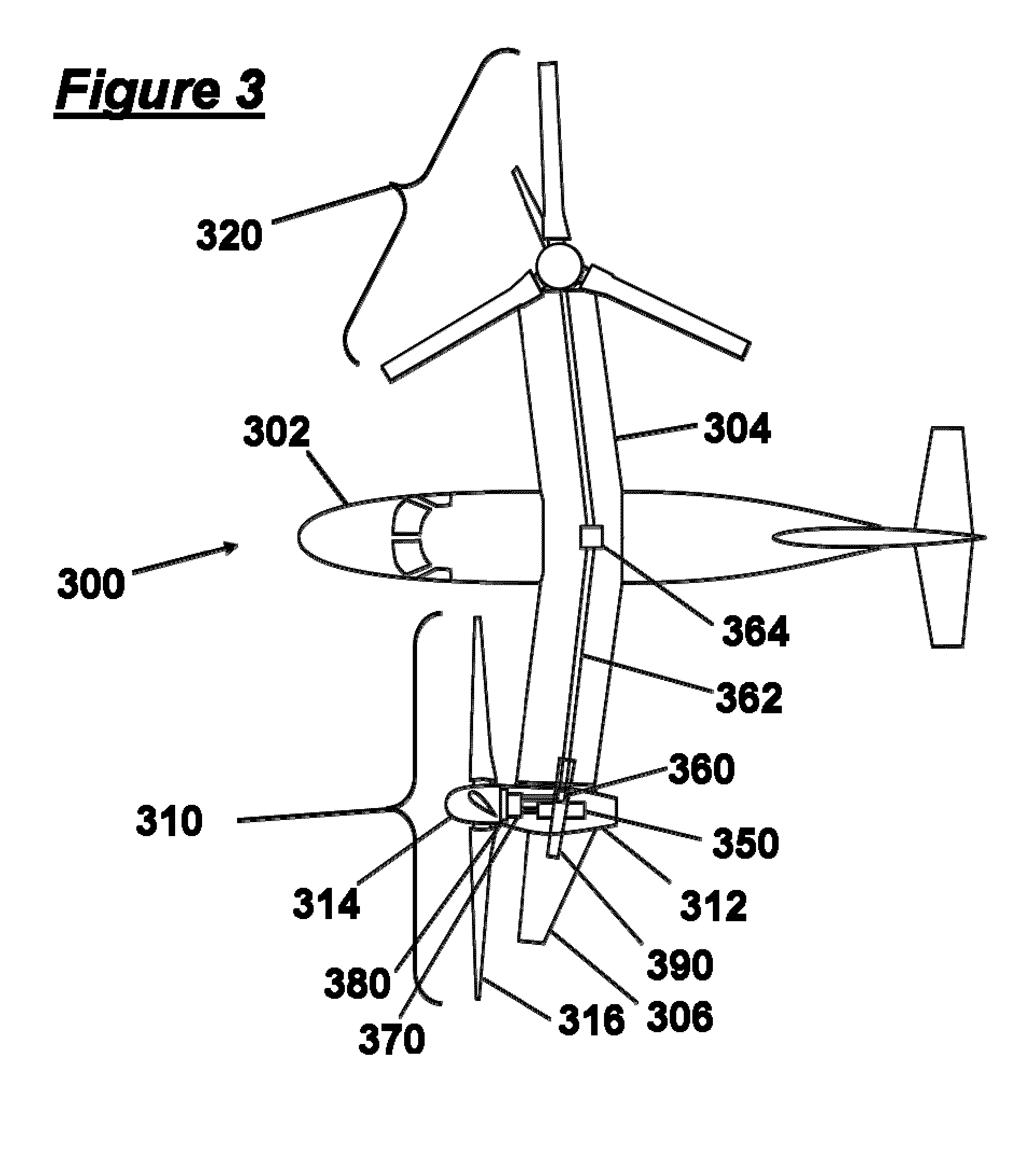
[0025]FIG. 3 is a schematic top view illustration of a preferred tiltrotor aircraft 300. The aircraft comprises a fuselage 302, inboard wing 304, first rotor system 310, and second rotor system 320. The second rotor system 320 is shown in a vertical orientation, consistent with helicopter-mode flight. The first rotor system 310 is shown in a horizontal orientation, consistent with airplane-mode cruise flight. In practice, the first rotor system 310 and second rotor system 320 are likely to have a substantially similar orientation at any given time in flight. An outboard wing 306 tilts with the nacelle 312.

[0026]A first rotor system 310 comprises a hub 314 coupled to a tilting nacelle 312, which tilts with respect t...


PUM


Abstract

An aircraft is equipped with a spinnion coupling an inboard wing to a tilting nacelle. The spinnion is advantageously configured to extend across the nacelle from an inboard junction to an outboard junction, and terminates inside the inboard wing. This provides an efficient lightweight structure to support a nacelle and facilitate tilting of the nacelle. The spinnion, which can be configured to be at least partially disposed within the inboard wing, is advantageously concentric with the tilting axis in order to facilitate tilting of a nacelle. A cross-wing driveshaft can be included, disposed at least partly within the inboard wing, and can advantageously be configured to terminate inside the spinnion at a junction with a miter gearbox. The miter gearbox can be disposed at least partly within the spinnion but more preferably lies entirely within the spinnion, and functions to transfer power from an input shaft to the cross-wing driveshaft.

Description

[0001]This application claims priority to U.S. Provisional Application Ser. No. 61 / 047,853 filed Apr. 25, 2008 which is incorporated by reference herein in its entirety.FIELD OF THE INVENTION[0002]The field of the invention is rotorcraft.BACKGROUND[0003]Tiltrotor aircraft are known in the prior art, including the Bell™ XV-3, XV-15, V-22, and BA609. Tiltrotor and tiltwing aircraft convert between a forward flight cruise mode and a hover mode by changing the orientation of their propellers or rotors and nacelles. Tilting of the nacelle or wing typically occurs about a pivot point commonly called the conversion spindle. The spindle is usually a circular pivot attached to the rotating structure (i.e. wing or nacelle) and inserted into the non-rotating fuselage or wing of the aircraft. For increased redundancy and reliability, the engine driving a rotor on one side of the aircraft is usually configured to have the capability of driving the rotor on the other side of the aircraft by linki...

Claims


Application Information

Patent Timeline
Patent Type & Authority Patents(United States)
IPC IPC(8): B64C27/22B64C39/00
CPCB64C3/185B64C29/0033
Inventor KAREM, ABE
Owner KAREM ABE
Why Eureka
Try Eureka