Wiper Blade

a wiper blade and wiper blade technology, applied in the field of windshield wiper devices, can solve the problems of generating annoying folding back noise, permanent deformation, and negatively affecting the wiper effect of windshield wipers

Active Publication Date: 2008-07-31
ROBERT BOSCH GMBH +1
View PDF3 Cites 4 Cited by
  • Summary
  • Abstract
  • Description
  • Claims
  • Application Information

AI Technical Summary

Problems solved by technology

An annoying folding-back noise is generated in particular in wiper blades with a spring elastic supporting element because of this folding-back process.
Over the course of the deployment time this leads to a permanent deformation of the wiper rubber profile, which at first only negatively impacts the wiping effect of the wi...

Method used


Image

  • Wiper Blade
  • Wiper Blade
  • Wiper Blade

Examples


Embodiment Construction

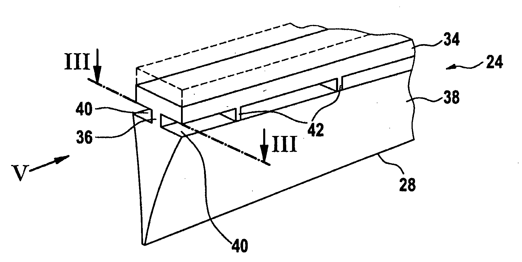
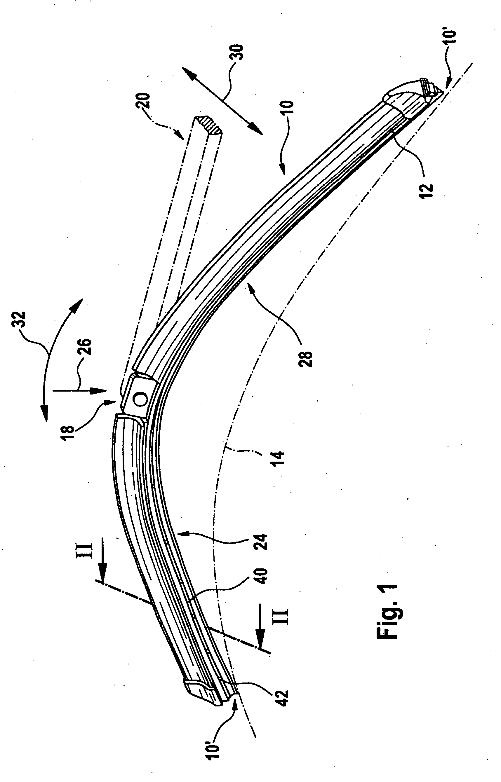
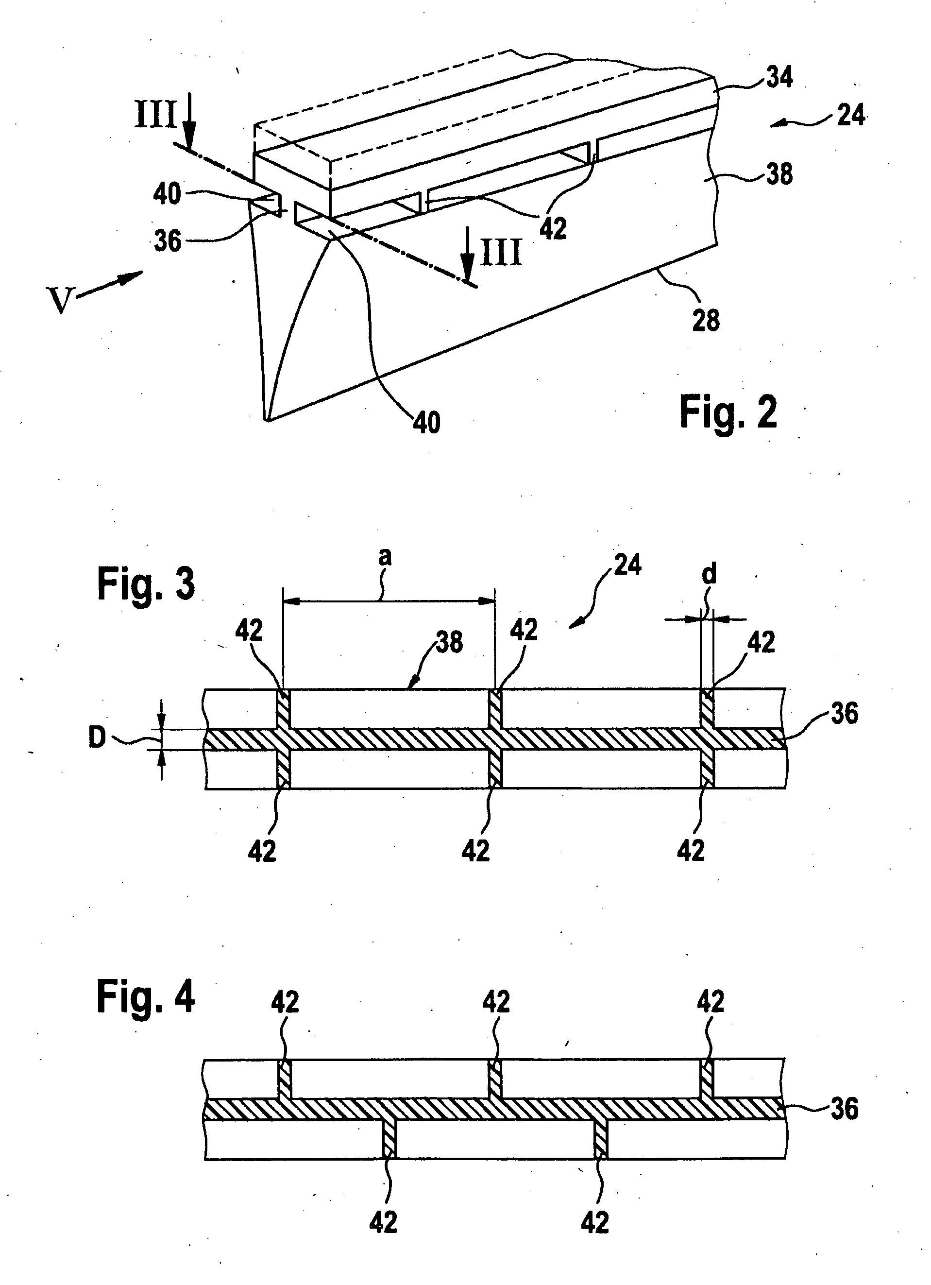
[0023]A wiper blade 10 depicted in FIG. 1 features a band-like, long-stretched-out, spring elastic single or multipart supporting element 12, which is curved in the longitudinal direction in an unstressed state. Arranged on the upper or external convex band side 16 (FIGS. 1 and 2) of the supporting element facing away from the to-be-wiped window 14 in the center section of said supporting element is, e.g., a flat, connecting device 18 that is adjacent to said band side. Said connecting device can be used to detachably connect the wiper blade 10 to a driven wiper arm 20 that is guided on the body of a vehicle. A long-stretched-out, rubber elastic wiper strip 24 is arranged on the lower or internal concave band surface or band side 22 of the curved supporting element 12 that faces the window and this wiper strip extends longitudinally axially parallel to the supporting element 12. Counter connecting means (not shown in greater detail) are provided on the free end of the wiper arm, and...


PUM


Abstract

The invention relates to a wiper blade (10) comprising a wiper strip (24) that is provided with a folding wedge (38) and a wiper strip back (34) that are connected to each other via a tilting web (36). It is proposed that additional webs (42) be arranged lateral to the tilting web (36).

Description

PRIOR ART[0001]The invention relates to a windshield wiper device in accordance with the species of the independent claim. In the case of such wiper blades with an elastic, band-like supporting element, said supporting element is supposed to guarantee the most uniform possible distribution of the wiper blade application force originating from the wiper arm on the window over the entire wiper field being covered by the wiper blade. Because of a corresponding curvature of the unstressed supporting element—i.e., when the wiper blade is adjacent to the window only at its two ends—the ends of the wiper strip that are applied completely to the window during wiper blade operation are stressed by the then tensioned supporting element on the window, even if the curvature radii of spherically curved vehicle windows change with every wiper blade position. The curvature of the wiper blade must therefore be somewhat greater than the greatest curvature measured in the wiper field on the to-be-wip...

Claims


Application Information

Patent Timeline
IPC IPC(8): B60S1/38
CPCB60S2001/3836B60S1/3848
Inventor DIETRICH, JANFANGMEIER, WILHELM
Owner ROBERT BOSCH GMBH
Why Eureka
Try Eureka