Device on a drafting system of a draw frame for textile fibre slivers

a technology of draw frame and textile fibre, which is applied in the direction of shaft and bearing, bearing components, textiles and paper, etc., can solve the problem that the bearing housing of the presser roll cannot be removed from the journal, and achieve the effect of simple, quick and reliabl

Inactive Publication Date: 2010-11-23
TRUETZSCHLER GMBH & CO KG
View PDF19 Cites 2 Cited by
  • Summary
  • Abstract
  • Description
  • Claims
  • Application Information

AI Technical Summary

Benefits of technology

[0005]It is an aim of the invention to provide a device of the kind described at the beginning which avoids or mitigates the mentioned disadvantages, which is structurally simple and which enables the bearing housings to be mounted on and removed from the presser roll in a simple, quick and reliable manner.
[0010]Because the bearing elements are in the form of rolling-element bearings, the functions of the rolling-element bearings and of the bearing element are advantageously fused with one another. The rolling-element bearing arrangement is integrated into the bearing housing. The coupling between the journals and the rotational bodies of the rolling-element bearing or bearing element provides an especially elegant way in which the bearing housings can be mounted on or removed from the presser roll in a simple, quick and reliable manner. At the same time, the coupling ensures reliable transmission of force between the rotational body and the journal, that is to say torque transmission with rapid disconnection and connection is advantageously realised. In accordance with a preferred construction, the common engagement surfaces of the journal and of the rotational body are each of tapered construction, which allows self-centring. A tapered connection transmits high torques with low axial forces and exhibits very low concentricity tolerances.

Problems solved by technology

A particular problem is that the bearing housing of the presser roll here cannot be removed from the journal.
The roller bearing and the ball bearing form separate components, which is expensive.

Method used


Image

  • Device on a drafting system of a draw frame for textile fibre slivers
  • Device on a drafting system of a draw frame for textile fibre slivers
  • Device on a drafting system of a draw frame for textile fibre slivers

Examples


Embodiment Construction

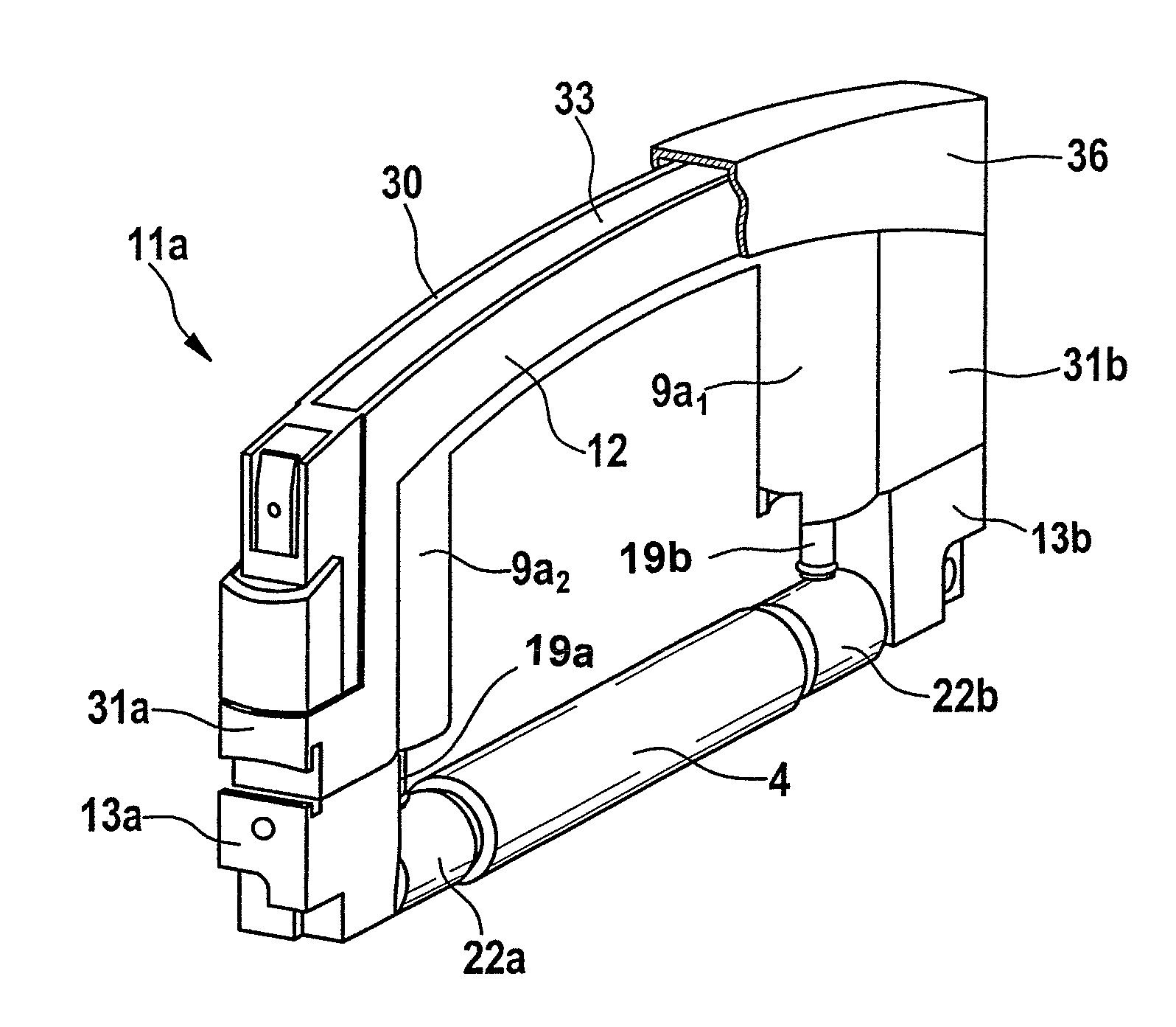
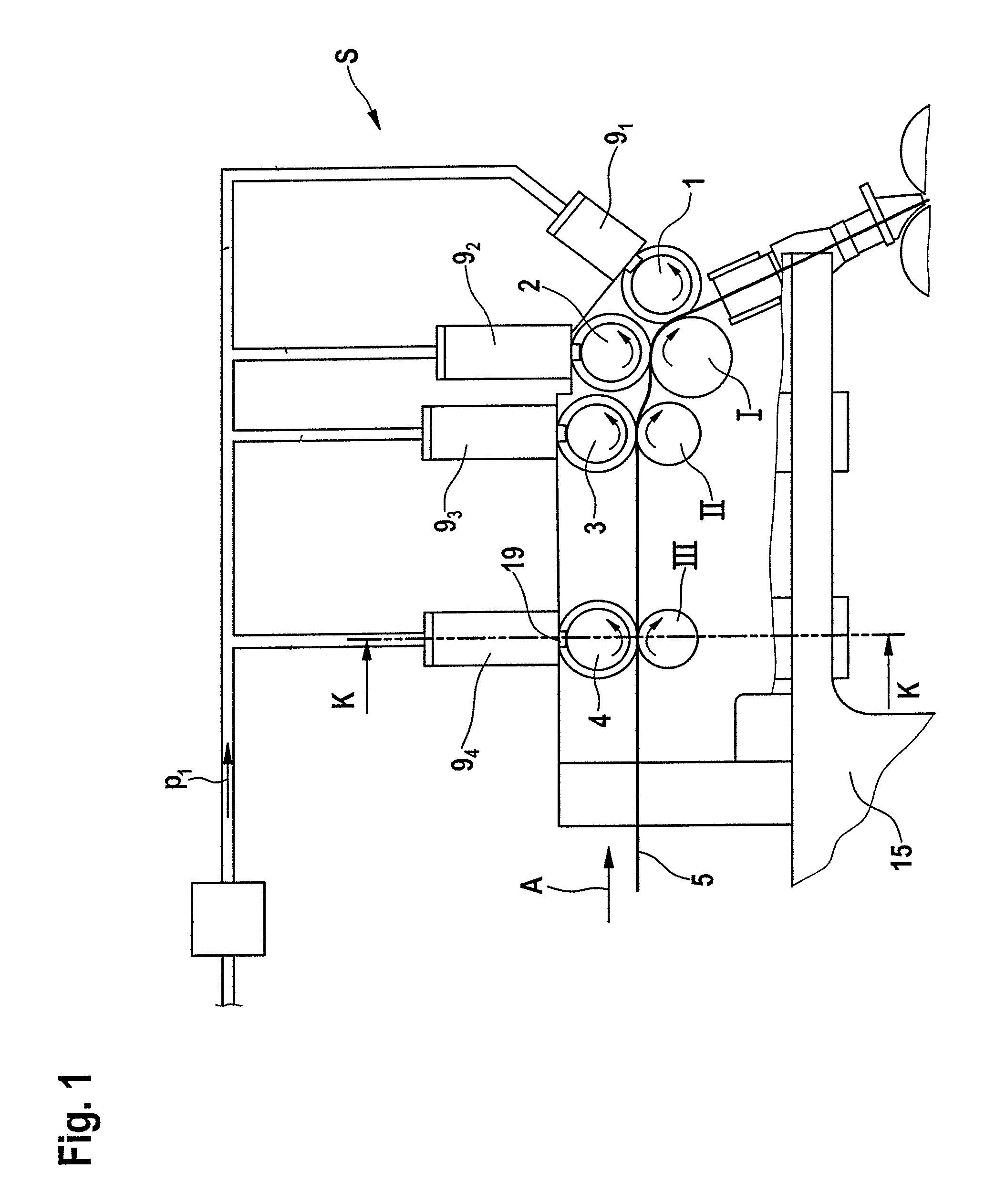
[0029]FIG. 1 shows a drafting system S of a draw frame, for example a draw frame TC 03 made by Trützschler GmbH & Co. Kg of Mönchengladbach, Germany. The drafting system S is configured as a 4 over 3 drafting system, that is to say it consists of three lower rolls I, II, III (I output lower roll, II middle lower roll, III input lower roll) and four upper rolls 1, 2, 3, 4. In the drafting system S, the drafting of the fibre bundle 5, which consists of a plurality of fibre slivers, is carried out. The drafting operation is composed of the preliminary drafting operation and the main drafting operation.

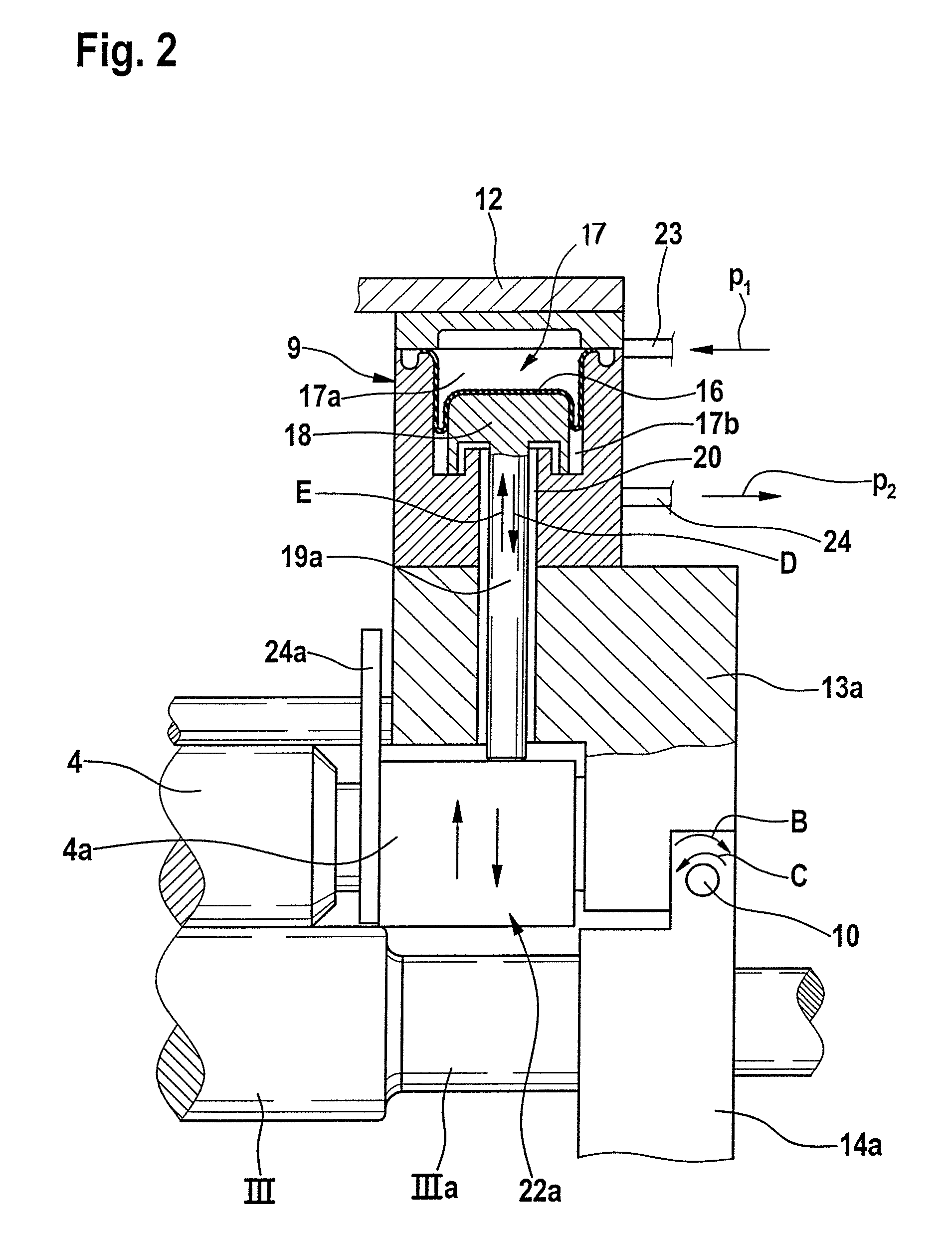
[0030]The roll pairs 4 / III and 3 / II form the preliminary drafting zone and the roll pairs 3 / II and 1,2 / I form the main drafting zone. The output lower roll I is driven by the main motor (not shown) and thus determines the delivery speed. The input and middle lower rolls III and II are driven by a regulating motor (not shown). The upper rolls 1 to 4 are pressed against the lower rolls I, I...


PUM

PropertyMeasurementUnit
axial shear forcesaaaaaaaaaa
displacementaaaaaaaaaa
forceaaaaaaaaaa

Abstract

In a device on a drafting system for textile fiber slivers with weighting of the upper rolls of the drafting system which comprises roll pairs arranged one behind the other, the pairs having lower and upper rolls, the rotating journals at the ends of the upper roll are mounted by means of bearing elements and the bearing elements each have at least one rolling-element bearing having an immovable outer housing (outer ring) and an internal rotational body (inner ring). In order to provide a structurally simple way in which the bearing housings can be mounted on or removed from the presser roll in a simple, quick and reliable manner, the bearing elements are in the form of rolling-element bearings and there is a coupling between the journal and the rotational body.

Description

CROSS-REFERENCE TO RELATED APPLICATION[0001]This application claims priority from German Patent Application No. 10 2007 039522.3 dated Aug. 21, 2007, the entire disclosure of which is incorporated herein by reference.BACKGROUND OF THE INVENTION[0002]The invention relates to a device on a drafting system of a draw frame for textile fibre slivers. In a known system there is weighting of the upper rolls of the drafting system which comprises roll pairs arranged one behind the other, the pairs having lower and upper rolls, and the rotating journals at the ends of the upper roll are mounted by means of bearing elements and the bearing elements each have at least one rolling-element bearing having an immovable outer housing (outer ring) and an internal rotational body (inner ring).[0003]In a drafting system according to German Patent Specification No 968 448, a rolling-element bearing arrangement is housed on each side of the presser roll in a special bearing housing which can be removed ...

Claims


Application Information

Patent Timeline
Patent Type & Authority Patents(United States)
IPC IPC(8): D01H5/74
CPCD01H5/56D01H5/565D01H5/22D01H5/52D01H5/74
Inventor SCHMITZ, THOMASILMBERGER, HELMUT
Owner TRUETZSCHLER GMBH & CO KG
Why Eureka
Try Eureka